
Data Sheet


MFRC522 All information provided in this document is subject to legal disclaimers. © NXP Semiconductors N.V. 2016. All rights reserved.
Product data sheet
COMPANY PUBLIC
Rev. 3.9 — 27 April 2016
112139 40 of 95
NXP Semiconductors
MFRC522
Standard performance MIFARE and NTAG frontend
9.3.1.6 DivIrqReg register
Interrupt request bits.
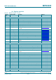
Table 30. ComIrqReg register bit descriptions
All bits in the ComIrqReg register are cleared by software.
Bit Symbol Value Description
7 Set1 1 indicates that the marked bits in the ComIrqReg register are set
0 indicates that the marked bits in the ComIrqReg register are cleared
6 TxIRq 1 set immediately after the last bit of the transmitted data was sent out
5 RxIRq 1 receiver has detected the end of a valid data stream
if the RxModeReg register’s RxNoErr bit is set to logic 1, the RxIRq bit is
only set to logic 1 when data bytes are available in the FIFO
4 IdleIRq 1 If a command terminates, for example, when the CommandReg changes
its value from any command to the Idle command (see Table 149 on
page 70)
if an unknown command is started, the CommandReg register
Command[3:0] value changes to the idle state and the IdleIRq bit is set
The microcontroller starting the Idle command does not set the IdleIRq
bit
3 HiAlertIRq 1 the Status1Reg register’s HiAlert bit is set
in opposition to the HiAlert bit, the HiAlertIRq bit stores this event and
can only be reset as indicated by the Set1 bit in this register
2 LoAlertIRq 1 Status1Reg register’s LoAlert bit is set
in opposition to the LoAlert bit, the LoAlertIRq bit stores this event and
can only be reset as indicated by the Set1 bit in this register
1 ErrIRq 1 any error bit in the ErrorReg register is set
0 TimerIRq 1 the timer decrements the timer value in register TCounterValReg to zero
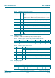
Table 31. DivIrqReg register (address 05h); reset value: x0h bit allocation
Bit 7 6 5 4 3 2 1 0
Symbol Set2 reserved MfinActIRq reserved CRCIRq reserved
Access W - D - D -
Table 32. DivIrqReg register bit descriptions
All bits in the DivIrqReg register are cleared by software.
Bit Symbol Value Description
7 Set2 1 indicates that the marked bits in the DivIrqReg register are set
0 indicates that the marked bits in the DivIrqReg register are cleared
6 to 5 reserved - reserved for future use
4 MfinActIRq 1 MFIN is active
this interrupt is set when either a rising or falling signal edge is
detected
3 reserved - reserved for future use
2 CRCIRq 1 the CalcCRC command is active and all data is processed
1 to 0 reserved - reserved for future use