
Data Sheet


MFRC522 All information provided in this document is subject to legal disclaimers. © NXP Semiconductors N.V. 2016. All rights reserved.
Product data sheet
COMPANY PUBLIC
Rev. 3.9 — 27 April 2016
112139 38 of 95
NXP Semiconductors
MFRC522
Standard performance MIFARE and NTAG frontend
9.3 Register descriptions
9.3.1 Page 0: Command and status
9.3.1.1 Reserved register 00h
Functionality is reserved for future use.
9.3.1.2 CommandReg register
Starts and stops command execution.
9.3.1.3 ComIEnReg register
Control bits to enable and disable the passing of interrupt requests.
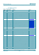
Table 21. Reserved register (address 00h); reset value: 00h bit allocation
Bit 7 6 5 4 3 2 1 0
Symbol reserved
Access -
Table 22. Reserved register bit descriptions
Bit Symbol Description
7 to 0 - reserved
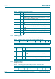
Table 23. CommandReg register (address 01h); reset value: 20h bit allocation
Bit 7 6 5 4 3 2 1 0
Symbol: reserved RcvOff PowerDown Command[3:0]
Access: - R/W D D
Table 24. CommandReg register bit descriptions
Bit Symbol Value Description
7 to 6 reserved - reserved for future use
5 RcvOff 1 analog part of the receiver is switched off
4 PowerDown 1 Soft power-down mode entered
0 MFRC522 starts the wake up procedure during which this bit is
read as a logic 1; it is read as a logic 0 when the MFRC522 is
ready; see Section 8.6.2 on page 33
Remark: The PowerDown bit cannot be set when the SoftReset
command is activated
3 to 0 Command[3:0] - activates a command based on the Command value; reading this
register shows which command is executed; see Section 10.3 on
page 70
Table 25. ComIEnReg register (address 02h); reset value: 80h bit allocation
Bit 7 6 5 4 3 2 1 0
Symbol IRqInv TxIEn RxIEn IdleIEn HiAlertIEn LoAlertIEn ErrIEn TimerIEn
Access R/W R/W R/W R/W R/W R/W R/W R/W