
Data Sheet


MFRC522 All information provided in this document is subject to legal disclaimers. © NXP Semiconductors N.V. 2016. All rights reserved.
Product data sheet
COMPANY PUBLIC
Rev. 3.9 — 27 April 2016
112139 32 of 95
NXP Semiconductors
MFRC522
Standard performance MIFARE and NTAG frontend
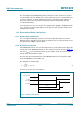
The timer can be started manually using the ControlReg register’s TStartNow bit and
stopped using the ControlReg register’s TStopNow bit.
The timer can also be activated automatically to meet any dedicated protocol
requirements by setting the TModeReg register’s TAuto bit to logic 1.
The delay time of a timer stage is set by the reload value + 1. The total delay time (t
d1
) is
calculated using Equation 5
:
(5)
An example of calculating total delay time (t
d
) is shown in Equation 6, where the
TPrescaler value = 4095 and TReloadVal = 65535:
(6)
Example: To give a delay time of 25 s requires 339 clock cycles to be counted and a
TPrescaler value of 169. This configures the timer to count up to 65535 time-slots for
every 25 s period.
The MFRC522 version 2.0 offers in addition a second prescaler timer. Due to the fact that
the prescaler counts down to 0 the prescaler period always count an odd number of
clocks (1, 3, 5, ..). This may lead to inaccuracy. The second available prescaler timer
implements the possibility to change the prescaler reload value to odd numbers, which
results in an even prescaler period. This new prescaler can be enabled only in version 2.0
using the register bit DemodeReg, see Table 72
. Within this option, the total delay time
(t
d2
) is calculated using Equation 5:
(7)
t
d1
TPrescaler 2 1+TReloadVal 1+
13.56 MHz
---------------------------------------------------------------------------------------------------------
=
39.59 s
4095 2 1+65535 1+
13.56 MHz
-----------------------------------------------------------------------
=
t
d2
TPrescaler 2 2+TReloadVal 1+
13.56 MHz
---------------------------------------------------------------------------------------------------------
=