
Data Sheet

MFRC522 All information provided in this document is subject to legal disclaimers. © NXP Semiconductors N.V. 2016. All rights reserved.
Product data sheet
COMPANY PUBLIC
Rev. 3.9 — 27 April 2016
112139 23 of 95
NXP Semiconductors
MFRC522
Standard performance MIFARE and NTAG frontend
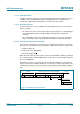
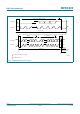
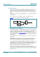
8.1.4.11 Switching between F/S mode and HS mode
After reset and initialization, the MFRC522 is in Fast mode (which is in effect F/S mode as
Fast mode is downward-compatible with Standard mode). The connected MFRC522
recognizes the “S 00001XXX A” sequence and switches its internal circuitry from the Fast
mode setting to the HS mode setting.
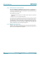
The following actions are taken:
1. Adapt the SDA and SCL input filters according to the spike suppression requirement
in HS mode.
2. Adapt the slope control of the SDA output stages.
It is possible for system configurations that do not have other I
2
C-bus devices involved in
the communication to switch to HS mode permanently. This is implemented by setting
Status2Reg register’s I
2
CForceHS bit to logic 1. In permanent HS mode, the master code
is not required to be sent. This is not defined in the specification and must only be used
when no other devices are connected on the bus. In addition, spikes on the I
2
C-bus lines
must be avoided because of the reduced spike suppression.
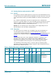
8.1.4.12 MFRC522 at lower speed modes
MFRC522 is fully downward-compatible and can be connected to an F/S mode I
2
C-bus
system. The device stays in F/S mode and communicates at F/S mode speeds because a
master code is not transmitted in this configuration.