
Data Sheet


MFRC522 All information provided in this document is subject to legal disclaimers. © NXP Semiconductors N.V. 2016. All rights reserved.
Product data sheet
COMPANY PUBLIC
Rev. 3.9 — 27 April 2016
112139 17 of 95
NXP Semiconductors
MFRC522
Standard performance MIFARE and NTAG frontend
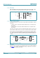
8.1.4.1 Data validity
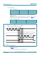
Data on the SDA line must be stable during the HIGH clock period. The HIGH or LOW
state of the data line must only change when the clock signal on SCL is LOW.
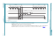
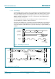
8.1.4.2 START and STOP conditions
To manage the data transfer on the I
2
C-bus, unique START (S) and STOP (P) conditions
are defined.
• A START condition is defined with a HIGH-to-LOW transition on the SDA line while
SCL is HIGH.
• A STOP condition is defined with a LOW-to-HIGH transition on the SDA line while
SCL is HIGH.
The I
2
C-bus master always generates the START and STOP conditions. The bus is busy
after the START condition. The bus is free again a certain time after the STOP condition.
The bus stays busy if a repeated START (Sr) is generated instead of a STOP condition.
The START (S) and repeated START (Sr) conditions are functionally identical. Therefore,
S is used as a generic term to represent both the START (S) and repeated START (Sr)
conditions.
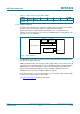
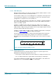
8.1.4.3 Byte format
Each byte must be followed by an acknowledge bit. Data is transferred with the MSB first;
see Figure 16
. The number of transmitted bytes during one data transfer is unrestricted
but must meet the read/write cycle format.
Fig 12. Bit transfer on the I
2
C-bus
mbc621
data line
stable;
data valid
change
of data
allowed
SDA
SCL
Fig 13. START and STOP conditions
mbc622
SDA
SCL
P
STOP condition
SDA
SCL
S
START condition