
Data Sheet


Revision 2.0 Page 71 of 74
nRF24L01 Product Specification
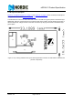
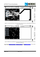
Figure 32. Top layer (nRF24L01 RF layout with single ended connection to PCB antenna and 0402 size
passive components)
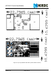
Figure 33. Bottom layer (nRF24L01 RF layout with single ended connection to PCB antenna and 0402
size passive components
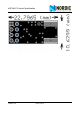
The nest figure (Figure 34. on page 72
, Figure 35. on page 72 and Figure 36. on page 73) is for the SMA
output to have a board for direct measurements at a 50Ω SMA connector.