
Data Sheet

Revision 2.0 Page 54 of 74
nRF24L01 Product Specification
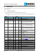
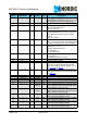
ERX_P3 3 0 R/W Enable data pipe 3.
ERX_P2 2 0 R/W Enable data pipe 2.
ERX_P1 1 1 R/W Enable data pipe 1.
ERX_P0 0 1 R/W Enable data pipe 0.
03 SETUP_AW Setup of Address Widths
(common for all data pipes)
Reserved 7:2 000000 R/W Only '000000' allowed
AW 1:0 11 R/W RX/TX Address field width
'00' - Illegal
'01' - 3 bytes
'10' - 4 bytes
'11' – 5 bytes
LSByte is used if address width is below 5 bytes
04 SETUP_RETR Setup of Automatic Retransmission
ARD 7:4 0000 R/W Auto Retransmit Delay
‘0000’ – Wait 250µS
‘0001’ – Wait 500µS
‘0010’ – Wait 750µS
……..
‘1111’ – Wait 4000µS
(Delay defined from end of transmission to start
of next transmission)
a
ARC 3:0 0011 R/W Auto Retransmit Count
‘0000’ –Re-Transmit disabled
‘0001’ – Up to 1 Re-Transmit on fail of AA
……
‘1111’ – Up to 15 Re-Transmit on fail of AA
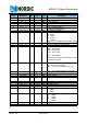
05 RF_CH RF Channel
Reserved 7 0 R/W Only '0' allowed
RF_CH 6:0 0000010 R/W Sets the frequency channel nRF24L01 operates
on
06 RF_SETUP RF Setup Register
Reserved 7:5 000 R/W Only '000' allowed
PLL_LOCK 4 0 R/W Force PLL lock signal. Only used in test
RF_DR 3 1 R/W Air Data Rate
‘0’ – 1Mbps
‘1’ – 2Mbps
RF_PWR 2:1 11 R/W Set RF output power in TX mode
'00' – -18dBm
'01' – -12dBm
'10' – -6dBm
'11' – 0dBm
LNA_HCURR 0 1 R/W Setup LNA gain
Address
(Hex)
Mnemonic Bit
Reset
Value
Type Description