
Data Sheet

Revision 2.0 Page 47 of 74
nRF24L01 Product Specification
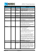
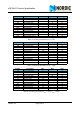
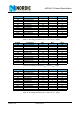
Table 16. Command set for the nRF24L01 SPI
The W_REGISTER and R_REGISTER commands can operate on single or multi-byte registers. When
accessing multi-byte registers you read or write to the MSBit of LSByte first. You can terminate the writing
before all bytes in a multi-byte register are written, leaving the unwritten MSByte(s) unchanged. For exam-
ple, the LSByte of RX_ADDR_P0 can be modified by writing only one byte to the RX_ADDR_P0 register. The
content of the status register is always read to MISO after a high to low transition on CSN.
Note: The 3 bit pipe information in the STATUS register is updated during the IRQ pin high to low
transition. If the STATUS register is read during an IRQ pin high to low transition, the pipe
information is unreliable.
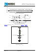
8.3.2 SPI timing
SPI operation and timing is shown in Figure 23. on page 47 to Figure 25. on page 48 and in Table 18. on
page 49 to Table 23. on page 50. nRF24L01 must be in one of the standby modes or in power down mode
before writing to the configuration registers.
In Figure 23. on page 47
to Figure 25. on page 48 the following abbreviations are used:
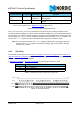
Table 17. Abbreviations used in Figure 23. to Figure 25.
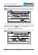
Figure 23. SPI read operation
W_TX_PAYLOAD_NO
ACK
a
1011 000 1 to 32
LSByte first
Used in TX mode. Disables AUTOACK on this
specific packet.
NOP 1111 1111 0 No Operation. Might be used to read the STATUS
register
a. To activate this feature use the ACTIVATE SPI command followed by data 0x73. The corresponding bits
in the
FEATURE register shown in Table 24. on page 58 have to be set.
Abbreviation Description
Cn SPI command bit
Sn STATUS register bit
Dn Data Bit (Note: LSByte to MSByte, MSBit in each byte first)
Command name
Command
word (binary)
# Data bytes Operation
C7 C6 C5 C4 C3 C2 C1 C0
S7 S6 S5 S4 S3 S2 S1 S0 D7 D6 D5 D4 D3 D2 D1 D0
D15
D14 D1 3 D1 2
D1 1 D1 0
D9 D8
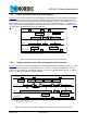
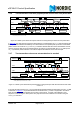
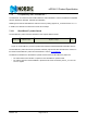
CSN
SCK
MOSI
MISO