
Data Sheet

Revision 2.0 Page 38 of 74
nRF24L01 Product Specification
7.8 Enhanced ShockBurst
TM
timing
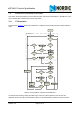
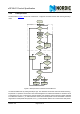
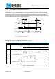
This section describes the timing sequence of Enhanced ShockBurst™ and how all modes are initiated
and operated. The Enhanced ShockBurst™ timing is controlled through the Data and Control interface.
The nRF24L01 can be set to static modes or autonomous modes where the internal state machine con-
trols the events. Each autonomous mode/sequence is ended with an interrupt at the IRQ pin. All the inter-
rupts are indicated as IRQ events in the timing diagrams.
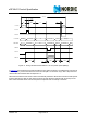
Figure 13. Transmitting one packet with NO_ACK on
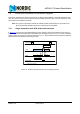
The following equations calculate various timing measurements:
Table 15. Timing equations
Symbol Description Equation
T
OA
Time on-air
T
ACK
Time on-air Ack
T
UL
Time Upload
T
ESB
Time Enhanced Shock-
Burst™ cycle
1 IRQ if No Ack is on.
T
IRQ
= 8.2ηs @ 1Mbps, T
IRQ
= 6.0ηs @ 2Mbps
Standby 1 PLL Lock TX
PTX IRQ
PTX MODE
UL
PTX CE
PTX SPI
T
OA
130usT
UL
IRQ:
TX DS
1
Standby-I
T
IRQ
>10us
[] [][ ] [] []
[]
s
bit
ratedataair
bitbytesorbytesNbytesorbyte
byte
bit
ratedataair
lengthpacket
T
fieldcontrolpacketCRCpayloadaddresspreamble
OA
92154,318 +
⎟
⎠
⎞
⎜
⎝
⎛
+++⋅
⎥
⎦
⎤
⎢
⎣
⎡
==
[] [ ][ ] [ ] []
[]
s
bit
ratedataair
bitbytesorbytesNbytesorbyte
byte
bit
ratedataair
lengthpacket
T
fieldcontrolpacketCRCpayloadaddresspreamble
ACK
92154,318 +
⎟
⎠
⎞
⎜
⎝
⎛
+++⋅
⎥
⎦
⎤
⎢
⎣
⎡
==
[]
[]
s
bit
ratedataSPI
bytesN
byte
bit
ratedataSPI
lengthpayload
T
payload
UL
⋅
⎥
⎦
⎤
⎢
⎣
⎡
==
8
IRQACKastbyULESB
TTTTT ++⋅+=
2
2