
Data Sheet

Revision 2.0 Page 31 of 74
nRF24L01 Product Specification
7.6 Enhanced ShockBurst flowcharts
This section shows flowcharts for PTX and PRX operation in Enhanced ShockBurst™. ShockBurst™ oper-
ation is marked with a dashed square in the flow charts.
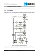
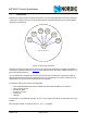
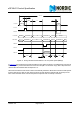
7.6.1 PTX operation
The flowchart in Figure 8. shows how a nRF24L01 configured as a PTX behaves after entering standby-I
mode.
Figure 8. PTX operations in Enhanced ShockBurst™
You activate PTX mode by setting the CE pin high. If there is a packet present in the TX FIFO the
nRF24L01 enters TX mode and transmits the packet. If Auto Retransmit is enabled, the state machine
Start Primary TX
Standby-I mode
Standby-II mode
Is CE=1?
Packet in TX
FIFO?
TX mode
Transmit Packet
Is Auto Re-
Transmit
enabled?
RX mode
Yes
Yes
Yes
No
Packet in TX
FIFO?
No
Is an ACK
received?
Timeout?
Has ARD
elapsed?
Yes
Standby-I mode
TX mode
Retransmit last
packet
TX Settling
Packet in TX
FIFO?
Yes
Is CE =1?
No
Is CE =1?
No
Yes
No
YesNo
Yes
TX Settling
Number of
retries = ARC?
No
RX Settling
Set MAX_RT IRQ
No
No
Yes
Set TX_DS IRQ
Yes
Has the ACK
payload?
Put payload in RX
FIFO.
Set TX_DS IRQ
and RX_DR IRQ
Set TX_DS IRQ
Yes
No
No_ACK?
No
Yes
NoYes
ShockBurst operation