
Data Sheet

Revision 2.0 Page 23 of 74
nRF24L01 Product Specification
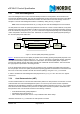
6.3 RF channel frequency
The RF channel frequency determines the center of the channel used by the nRF24L01. The channel
occupies a bandwidth of 1MHz at 1Mbps and 2MHz at 2Mbps. nRF24L01 can operate on frequencies from
2.400GHz to 2.525GHz. The resolution of the RF channel frequency setting is 1MHz.
At 2Mbps the channel occupies a bandwidth wider than the resolution of the RF channel frequency setting.
To ensure non-overlapping channels in 2Mbps mode, the channel spacing must be 2MHz or more. At
1Mbps the channel bandwidth is the same as the resolution of the RF frequency setting.
The RF channel frequency is set by the RF_CH register according to the following formula:
F
0
= 2400 + RF_CH [MHz]
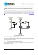
A transmitter and a receiver must be programmed with the same RF channel frequency to be able to com-
municate with each other.
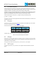
6.4 PA control
The PA control is used to set the output power from the nRF24L01 power amplifier (PA). In TX mode PA
control has four programmable steps, see Table 14.
The PA control is set by the RF_PWR bits in the RF_SETUP register.
Conditions: VDD = 3.0V, VSS = 0V, T
A
= 27ºC, Load impedance = 15Ω+j88Ω.
Table 14. RF output power setting for the nRF24L01
6.5 LNA gain
The gain in the Low Noise Amplifier (LNA) in the nRF24L01 receiver is controlled by the LNA gain setting.
The LNA gain makes it possible to reduce the current consumption in RX mode with 0.8mA at the cost of
1.5dB reduction in receiver sensitivity.
The LNA gain has two steps and is set by the LNA_HCURR bit in the RF_SETUP register.
6.6 RX/TX control
The RX/TX control is set by PRIM_RX bit in the CONFIG register and sets the nRF24L01 in transmit/
receive.
SPI RF-SETUP
(RF_PWR)
RF output power
DC current
consumption
11 0dBm 11.3mA
10 -6dBm 9.0mA
01 -12dBm 7.5mA
00 -18dBm 7.0mA