
Data Sheet

Revision 2.0 Page 22 of 74
nRF24L01 Product Specification
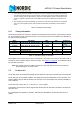
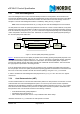
Table 12. nRF24L01 main modes
6.1.7 Timing Information
The timing information in this section is related to the transitions between modes and the timing for the CE
pin. The transition from TX mode to RX mode or vice versa is the same as the transition from standby-I to
TX mode or RX mode,Tstby2a.
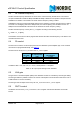
Table 13. Operational timing of nRF24L01
When nRF24L01 is in power down mode it must settle for 1.5ms before it can enter the TX or RX modes. If
an external clock is used this delay is reduced to 150µs, see Table 13. on page 22
. The settling time must
be controlled by the MCU.
Note: The register value is lost if VDD is turned off. In this case, nRF24L01 must be configured
before entering the TX or RX modes.
6.2 Air data rate
The air data rate is the modulated signaling rate the nRF24L01 uses when transmitting and receiving data.
The air data rate can be 1Mbps or 2Mbps. The 1Mbps data rate gives 3dB better receiver sensitivity com-
pared to 2Mbps. High air data rate means lower average current consumption and reduced probability of
on-air collisions.
The air data rate is set by the RF_DR bit in the RF_SETUP register.
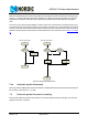
A transmitter and a receiver must be programmed with the same air data rate to be able to communicate
with each other.
For compatibility with nRF2401A, nRF24E1, nRF2402 and nRF24E2 the air data rate must be set to
1Mbps.
a. In this operating mode if the CE is held high the TX FIFO is emptied and all necessary ACK and pos-
sible retransmits are carried out. The transmission continues as long as the TX FIFO is refilled. If the
TX FIFO is empty when the CE is still high, nRF24L01 enters standby-II mode. In this mode the trans-
mission of a packet is started as soon as the
CSN is set high after a upload (UL) of a packet to TX
FIFO.
b. This operating mode pulses the
CE high for at least 10µs. This allows one packet to be transmitted.
This is the normal operating mode. After the packet is transmittet, the nRF24L01 enters standby-I
mode.
Name nRF24L01 Max. Min. Comments
Tpd2stby Power Down Î Standby mode 1.5ms Internal crystal
oscillator
Tpd2stby Power Down Î Standby mode 150µs With external
clock
Tstby2a Standby modes Î TX/RX mode 130µs
Thce Minimum CE high 10µs
Tpece2csn Delay from CE pos. edge to CSN low 4µs