
Data Sheet

Revision 2.0 Page 21 of 74
nRF24L01 Product Specification
The register values are maintained during standby modes and the SPI may be activated. For start up time
see Table 13. on page 22
.
6.1.4 RX mode
The RX mode is an active mode where the nRF24L01 radio is a receiver. To enter this mode, the
nRF24L01 must have the PWR_UP bit set high, PRIM_RX bit set high and the CE pin set high.
In this mode the receiver demodulates the signals from the RF channel, constantly presenting the demod-
ulated data to the baseband protocol engine. The baseband protocol engine constantly searches for a
valid packet. If a valid packet is found (by a matching address and a valid CRC) the payload of the packet
is presented in a vacant slot in the RX FIFO. If the RX FIFO is full, the received packet is discarded.
The nRF24L01 remains in RX mode until the MCU configures it to standby-I mode or power down mode. If
the automatic protocol features (Enhanced ShockBurst™) in the baseband protocol engine are enabled,
the nRF24L01 can enter other modes in order to execute the protocol.
In RX mode a carrier detect signal is avaliable. The carrier detect is a signal that is set high when a RF sig-
nal is detected inside the receiving frequency channel. The signal must be FSK modulated for a secure
detection. Other signals can also be detected. The Carrier Detect (CD) is set high when an RF signal is
detected in RX mode, otherwise CD is low. The internal CD signal is filtered before presented to CD register.
The RF signal must be present for at least 128µs before the CD is set high. How to use the CD is described
in Appendix E on page 74
.
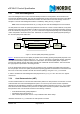
6.1.5 TX mode
The TX mode is an active mode where the nRF24L01 transmits a packet. To enter this mode, the
nRF24L01 must have the PWR_UP bit set high, PRIM_RX bit set low, a payload in the TX FIFO and, a high
pulse on the CE for more than 10µs.
The nRF24L01 stays in TX mode until it finishes transmitting a current packet. If CE = 0 nRF24L01 returns
to standby-I mode. If CE = 1, the next action is determined by the status of the TX FIFO. If the TX FIFO is
not empty the nRF24L01 remains in TX mode, transmitting the next packet. If the TX FIFO is empty the
nRF24L01 goes into standby-II mode.The nRF24L01 transmitter PLL operates in open loop when in TX
mode. It is important to never keep the nRF24L01 in TX mode for more than 4ms at a time. If the auto
retransmit is enabled, the nRF24L01 is never in TX mode long enough to disobey this rule.
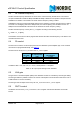
6.1.6 Operational modes configuration
The following table (Table 12.) describes how to configure the operational modes.
Mode
PWR_UP
register
PRIM_RX
register
CE FIFO state
RX mode111-
TX mode 1 0 1 Data in TX FIFO. Will empty all lev-
els in TX FIFO
a
.
TX mode 1 0 minimum 10μs
high pulse
Data in TX FIFO.Will empty one
level in TX FIFO
b
.
Standby-II 1 0 1 TX FIFO empty
Standby-I 1 - 0 No ongoing packet transmission
Power Down 0 - - -