
Data Sheet

Revision 2.0 Page 19 of 74
nRF24L01 Product Specification
6 Radio Control
This chapter describes the different modes the nRF24L01 radio transceiver can operate in and the param-
eters used to control the radio.
The nRF24L01 has a built-in state machine that controls the transitions between the different operating
modes of the chip. The state machine takes input from user defined register values and internal signals.
6.1 Operational Modes
The nRF24L01 can be configured in four main modes of operation. This section describes these modes.
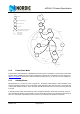
6.1.1 State diagram
The state diagram (Figure 3.) shows the modes the nRF24L01 can operate in and how they are accessed.
The nRF24L01 is undefined until the VDD becomes 1.9V or higher. When this happens nRF24L01 enters
the Power on reset state where it remains in reset until it enters the Power Down mode. Even when the
nRF24L01 enters Power Down mode the MCU can control the chip through the SPI and the Chip Enable
(CE) pin Three types of states are used in the state diagram. “Recommended operating mode” is a state
that is used during normal operation. “Possible operating mode” is a state that is allowed to use, but it is
not used during normal operation. “Transition state” is a time limited state used during start up of the oscil-
lator and settling of the PLL.