
Data Sheet

Revision 2.0 Page 15 of 74
nRF24L01 Product Specification
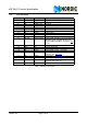
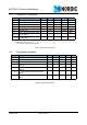
5.2 General RF conditions
Table 5. General RF conditions
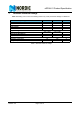
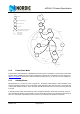
5.3 Transmitter operation
Table 6.Transmitter operation
Symbol Parameter (condition) Notes Min. Typ. Max. Units
f
OP
Operating frequency
a
a. Usable band is determined by local regulations
2400 2525 MHz
PLL
res
PLL Programming resolution 1 MHz
f
XTAL
Crystal frequency 16 MHz
Δf
1M
Frequency deviation @ 1Mbps ±160 kHz
Δf
2M
Frequency deviation @ 2Mbps ±320 kHz
R
GFSK
Air Data rate
b
b. Data rate in each burst on-air
1000 2000 kbps
F
CHAN-
NEL 1M
Non-overlapping channel spac-
ing @ 1Mbps
c
c. The minimum channel spacing is 1Mhz
1MHz
F
CHAN-
NEL 2M
Non-overlapping channel spac-
ing @ 2Mbps
c
2MHz
Symbol Parameter (condition) Notes Min. Typ. Max. Units
P
RF
Maximum Output Power
a
a. Antenna load impedance = 15Ω+j88Ω
0+4dBm
P
RFC
RF Power Control Range 16 18 20 dB
P
RFCR
RF Power Accuracy ±4 dB
P
BW2
20dB Bandwidth for Modulated Carrier
(2Mbps)
1800 2000 kHz
P
BW1
20dB Bandwidth for Modulated Carrier
(1Mbps)
900 1000 kHz
P
RF1
1
st
Adjacent Channel Transmit Power
2MHz
-20 dBm
P
RF2
2
nd
Adjacent Channel Transmit Power
4MHz
-50 dBm