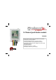
8-Channel push button module VMB8PB Can be used to connect any type of push button to the VELBUS Connection for up to 8 push buttons Push button reaction time: 65ms, 1s, 2s and 3 seconds. Connection possibility for a LED parallel to the push button. LED indication for each push button: backlight, slow, fast, very fast blinking and continuous 252 possible addresses Required power supply: 12 .. 18VDC Consumption: 30mA max.
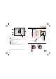
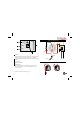
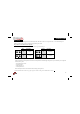
(red 2 3 4 5 Velbus 12V supply Push button connections Adress setting Enter a unique address (from ‘00’ to ‘FE’ except for ‘F0’, ‘F1’, ‘F2’, ‘F3’ and ‘FF’) for each module For a more elaborate connection example, see page 13 2 COM COM 8 7 6 5 4 3 2 1 7 89 A BUS + 12V - L TERM H A COM 1 Termination If the module is connected at the start or end of a cable on the VELBUS, place the ‘TERM’ jumper.
ENGLISH REACTION TIME The push buttons have a default short reaction time (65ms). There is possibility to maintain the push button pressed for 1, 2 or 3 seconds until they are considered as being closed. Follow this procedure: 1.
1 Afsluiting Indien de module op het begin of het einde van de VELBUSkabel aangesloten is, moet de ‘TERM’ jumper geplaatst worden. In alle andere gevallen moet deze verwijderd worden. 2 Velbus 3 12V voeding 4 Drukknop ingangen 5 Adresinstelling Stel een uniek adres in voor elke module via de ‘ADDR’ draaischakelaars van ‘00’ tot ‘FE’ uitgezonderd ‘F0’, ‘F1’, ‘F2’, ‘F3’ en ‘FF’ Uitgebreider aansluitingsvoorbeeld pag.
NEDERLANDS REACTIETIJD Standaard hebben de drukknoppen een korte reactietijd (65ms). Men kan er echter voor zorgen dan men 1, 2 of 3 seconden lang een drukknop ingeduwd moet houden vooraleer deze als gesloten gezien wordt. De procedure om dit te bekomen is de volgende: 1.
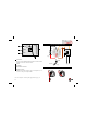
(rouge) Pour un exemple de connexion plus approfondi, voir page 13 6 COM COM 8 7 6 5 4 3 2 1 BUS + 12V - L TERM LED (blanc) K A 3 12V supply 5 Réglage d’adresse Attribuez une adresse unique (de ‘00’ à ‘FE’ excepté ‘F0’, ‘F1’, ‘F2’, 'F3' et ‘FF’) pour chaque module 7 89 A COM Placez le cavalier TERM uniquement dans un module connecté au début ou en fin de connexion Velbus.
FRANCAIS DÉLAI DE RÉACTION Les boutons poussoirs ont un court délai de réaction (65ms) par défaut. Il est possible de faire en sorte qu’on soit obligé de maintenir enfoncé un bouton poussoir pendant 1, 2 ou 3 secondes avant que celui-ci soit considéré comme étant fermé. Voici la procédure: 1.
(rot) Umfangreicheres Anschlussbeispiel Seite 13 8 COM COM 8 7 6 5 4 3 2 1 BUS + 12V - L TERM LED (Weiss) K A 3 12V-Stromversorgung 5 Adresseneinstellung Stellen Sie eine einzigartige Adresse für jedes Module ein über die 'ADDR' Drehschalter von ‘00’ bis ‘FE’ ausgenommen ‘F0’, ‘F1’, ‘F2’, 'F3' en ‘FF’. 7 89 A COM Montieren Sie die TERM-Steckbrücke bei einem Modul am Anfang oder am Ende des Velbus-Anschlusses.
DEUTCH REAKTIONZEIT Die Druckknöpfe haben standardmäßig eine kurze Reaktions-zeit (65ms). Man kann jedoch dafür sorgen, dass man den Druckknopf 1, 2 oder 3 Sekunden gedrückt halten muss, bevor er als geschlossen betrachtet wird. Vorgehensweise: 1.
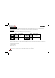
1 Terminación Ponga el jumper TERM sólo en un módulo conectada al principio o al extremo de conexión Velbus. Borre el jumper en todos los otros módulos. 2 Velbus 3 Alimentación 12V 4 Entradas pulsadores 5 Ajuste de dirección Introduzca una sola dirección para cada módulo con los interruptores giratorios hexadecimales de ‘00’ a ‘FE’ salvo ‘C1’, ‘D1’, ‘E1’, 'F3' y ‘FF’. ejemplo de conexión más extenso p.
ESPAÑOL TIEMPO DE REACCIÓN Los pulsadores tienen un corto tiempo de reacción (65ms) por defecto. Sin embargo, es posible cerrar los contactos de entrada durante 1, 2 ó 3 segundos antes de que el módulo se dé cuenta. Siga el siguiente procedimiento: 1.
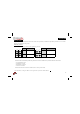
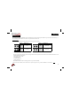
CONNECTION EXAMPLE - AANSLUITINGSVOORBEELD - EXEMPLE DE CONNEXION ANSCHLUSSBEISPIEL - EJEMPLO DE CONEXIÓN
UK For connection between the modules, use twisted pair cable (ex. EIB 2x2x0.8mm2, UTP 8x0.51mm - CAT5 or other). Use minimum 0.5mm² cable. For long wiring (>50m) or if a lot of modules ( > 10) are connected to one wire, use 1mm² cable. Connect the 12 to 18VDC (mind the polarity) to the module. Connect the bus (mind the polarity) to the module. Cable the push buttons. We advise to insulate connections which are not used.
VMB8PB L H H L BUS + 12V - COM COM 8 7 6 5 4 3 2 1 PUSH BUTTON 8 C PUSH BUTTON 7 C PUSH BUTTON 6 C PUSH BUTTON 5 C PUSH BUTTON 4 C PUSH BUTTON 3 C -12V+ BUS TWISTED PAIR (0.
VELLEMAN Components NV Legen Heirweg 33 9890 Gavere Belgium Europe www.velleman.be www.velleman-kit.com www.velbus.be Modifications and typographical errors reserved - © Velleman Components nv.