Level and Pressure Operating instructions VEGACOM 557 VEGA ASCII protocol PC BA on 557 in out
Contents Contents Safety information ..................................................................................................... 2 Note Ex area ............................................................................................................. 2 1 Product description 1.1 Application ......................................................................................................... 4 1.2 Configuration ................................................................................
Contents 3 Switch settings on VEGACOM 557 3.1 Adjustment of the PC interface ...................................................................... 20 3.2 Adjustment of the VEGA ASCII interface ...................................................... 21 4 Data image in VEGACOM 557 4.1 Enquiry for VEGAMET with three or less values per instrument ................ 26 4.2 Enquiry for VEGAMET with up to seven values per instrument ................. 28 4.3 Enquiry as block with low resolution ...................
Product description 1 Product description 1.1 Application 1.2 Configuration The VEGACOM 557 is an efficient and easyto-use interface converter (Gateway) for your measurement applications. It is used for conversion of the VEGA-specific protocols of DISBUS and LOGBUS into standard data formats. The component VEGACOM 557 is designed in 19" technology with 5 TE width (1 TE = 5.08 mm) acc. to DIN 41 494. It can be used: - in carrier BGT 596 - in VEGALOG 571 carrier BGT LOG 571 - in housing type 505.
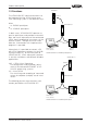
Product description 1.3 Functions The VEGACOM 557 interface converter can be integrated into the VEGA level or pressure measuring system in two different ways: VEGAMET DISBUS % 100 + - ESC OK CONNECT ! on VEGAMET 513 either - as DISBUS participant or - as LOGBUS participant. VEGACOM 557 PC BA ! on In both cases, VEGACOM 557 operates as passive participant and provides measured data and status information of the connected VEGA signal conditioning instruments via the external system.
Product description VEGACOM 557 on DISBUS VEGAMET series 500/600 signal conditioning instruments transmit via the DISBUS cyclically measured data and status information, so called PC/DCS telegrams. VEGACOM 557 receives these data as participant on the DISBUS and makes them available (in buffer memory) for collection via the VEGA ASCII protocol. VEGACOM 557 on LOGBUS Data are exchanged continuously on the LOGBUS between the individual components of VEGALOG 571.
Product description VEGACOM 557 with VEGA ASCII The data communication between VEGACOM 557 and a master is only carried out if initiated by the master, which can enquire the requested information by means of special commands. The data from DISBUS/LOGBUS are first written in a buffer memory of VEGACOM 557. The data set is transferred from this buffer memory into a process image. The protocol conversion software enquires the stored data cyclically from the individual storage areas.
Product description Complete measuring system with digital communication and networking DISBUS on % 100 % 100 % 100 % 100 % 100 % 100 % 100 % 100 - + - + - + - + - + - + - + - + ESC OK ESC OK ESC OK ESC OK ESC OK ESC OK ESC OK ESC OK CONNECT ! CONNECT ! on 513 CONNECT ! on VEGAMET 513 CONNECT ! on VEGAMET VEGAMET 513 CONNECT ! on on VEGAMET 513 CONNECT ! on VEGAMET 513 CONNECT ! on VEGAMET 513 CONNECT ! on VEGAMET VEGAMET 513 513 E
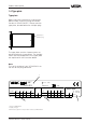
Product description 1.4 Type plate Type plate Before mounting and electrical connection, please check if you are using the correct version of VEGACOM 557. Please note the type plate, located below the multiple plug. Type plate on multiple plug The type plate contains important data required for electrical connection. The configuration and the components of the type plate are explained in the illustration below. Note: The serial number of your VEGACOM is on the rear of the plug connector.
Product description 1.5 Technical data Power supply Supply voltage Power consumption Fuse Unom = 24 V AC (20 … 53 V), 50/60 Hz or = 24 V DC (20 … 72 V) approx. 6 VA 1 A, slow-blow Electrical connection Component Module in carrier BGT 596 or BGT LOG 571 Housing type 505 multiple plug acc. to DIN 41 612, series F 48 pole (d, b, z) with coding holes suitable multipoint connector acc. to DIN 41 612 with connection via standard technologies via screw terminals max. 1 x 1.
Product description Modbus ASCII-mode Coding system Number of bits Parity Backup hexadecimal, ASCII-character 1 start bit, 7 or 8 data bits, 1 (0) parity bit, 1 stop bit NONE, ODD, EVEN none Electrical protective measures Protection: not mounted in carrier BGT 596 or BGT LOG 571 - front side completely equipped - upper and lower side BGT 596 BGT LOG 571 - wiring side in housing type 505 - front side - other sides Protection class Overvoltage category IP 00 IP 40 IP 00 IP 20 IP 00 IP 40 IP 30 II (in hous
Product description 1.6 Dimensions Multiple plug LOGBUS plug 5 TE 128,4 Multipoint connector 100 x 160 x 1.
Product description 1.7 Indicating and adjustment elements As diagnostic aid, VEGACOM 557 is equipped with three LEDs. These are located on the instrument front panel. In addition, the basic board, as well as the additional board of VEGACOM 557 are equipped with a number of switches (DIP switch or hook switch) for configuration of the available interfaces. Adjustment elements The adjustment elements are located on the basic board.
Mounting and electrical connection 2 Mounting and electrical connection 2.1 Mounting instructions The gateway VEGACOM 557 can process measured data and status information in two different ways: - via DISBUS (from measuring systems with VEGAMET) - via LOGBUS (from measuring systems with VEGALOG). Instrument coding Function coding VEGACOM 557 a27 c3/c11 Instrument coding Function coding d b z a c 1 For DISBUS configurations, VEGACOM 557 can be either mounted into carrier BGT 596 or housing type 505.
Mounting and electrical connection 2.2 Mounting in carrier and housing 2.3 Wiring plan VEGACOM 557 BGT 596 or BGT LOG 571 PC interface in front panel (SUB-Dplug) For mounting, a slot module must be provided at the location. A slot module consists of: - a multipoint connector acc. to DIN 41 612, series F, 33-pole (d, b, z) - two screws - three coded pins - two guide rails. The multipoint connector is available in the following versions: - Wire-Wrap, standard connection 1.0 mm x 1.
Mounting and electrical connection Connection via modem For remote parameter adjustment, it is possible to connect the PC interface via a modem. In such a case, the modem cable that comes with the respective modem should be used. Modem operation is supported by VEGACOM 557 from software version 2.11. Further information on the remote parameter adjustment is stated in the operating instructions "Remote parameter adjustment“.
Mounting and electrical connection Modbus via TTY Supply voltage d b z + – 2.4 Mounting and installation instructions with VEGACOM 557AP As an option, VEGACOM 557 can be extended with the adapter print VEGACOM 557AP. The adapter print VEGACOM 557AP consists of a module card with 5 TE width and two modules connected to a back-panel print for carrier BGT 596 or BGT LOG 571.
Mounting and electrical connection Make sure that also VEGACOM 557 is set to the same interface type (DIL-switch 1 on the additional board) as VEGACOM 557AP. The pin assignments of SUB-D-plug and SUB-Dsocket is listed in the tables. Pin assignments VEGACOM 557AP Pin-Nr.
Mounting and electrical connection Terminals for supply voltage Ub+ Terminals for DISBUS View of back-panel board (rear of the carrier) VEGA ASCII interface of VEGACOM 557 as SUB-D-plug PC interface of VEGACOM 557 PC VEGA ASCII interface of VEGACOM 557 as SUBD-socket BA on 557 557AP Front view with SUB-D-connections of VEGACOM 557 and VEGACOM 557AP VEGACOM 557 VEGA ASCII 19
Switch settings on VEGACOM 557 3 Switch settings on VEGACOM 557 For adjustment of the interfaces or the BUS parameters of the PC interface and the VEGA ASCII interfaces, various DIL switches are provided on VEGACOM 557. Before inserting VEGACOM 557 into the carrier or the housing, the DIL switches must be set according to the user-specific data. The data of these settings will be effective with the next initialization (switching on of voltage). 3.
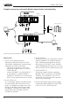
Switch settings on VEGACOM 557 DIL switch block 1 (additional board) 3.2 Adjustment of the VEGA ASCII interface DIL switch blocks additional board Additional board 1 2 3 Hook switches additional board 2 1 1 2 3 4 5 6 7 8 ON Three 8-pole DIL switch blocks as well as two hook switches for configuration of the VEGA ASCII interface to the DCS or the PLC are located on the additional board.
Switch settings on VEGACOM 557 DIL switch block 2 (additional board) 1 2 3 4 5 6 7 8 ON DCS measured value image (only relevant on VEGAMETs) all meas. values Met 1, all meas. values Met 2, etc. 1. meas. value Met 1, 1. meas. value Met 2, etc. Protocol mode Modbus ASCII Modbus RTU Parity none 1 2 3 4 5 6 7 8 ON Factory setting DIL switch block 3 (additional board) Factory setting Bus address of VEGACOM 557 (Adr. 1 to 9) e.g.: Adr.
Switch settings on VEGACOM 557 Depending on the requirements, the VEGA ASCII interface can be used as TTY interface but also as RS 232 interface (using the hook switches). Illustration 2.15 shows the respective switch positions. As a rule, VEGACOM 557 is delivered with RS 232 activated.
Data image in VEGACOM 557 4 Data image in VEGACOM 557 VEGACOM 557 collects the measured values of the VEGA signal conditioning instruments VEGAMET 509, 512, 513, 514, 515 and 614 (via DISBUS) or VEGALOG 571 (via LOGBUS) and puts them in the temporary memory for collection via the VEGA ASCII. Due to these two different series, it is necessary to use two different telegrams for the enquiry of measured values. With enquiry "P“ 3 values are transmitted.
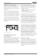
Data image in VEGACOM 557 Enquiry of DCS values on LOGBUS all measured values of VEGAMET #1 all measured values of VEGAMET #2 all measured values of VEGAMET #15 % 100 % 100 % 100 % 100 - + - + - + - + ESC OK ESC OK ESC OK ESC OK CONNECT CONNECT ! CONNECT ! on CONNECT ! on VEGAMET ! on VEGAMET 513 The numbering of the DCS values is made for LOGBUS between 001 and 255. This assignment is prepared via the parameter tool VVO. Each DCS value is therefore marked clearly.
Data image in VEGACOM 557 4.1 Enquiry for VEGAMET with three or less values per instrument Low resolution = Switch 2.2 = OFF VEGAMET series 509 and 512 instruments have max. 3 DCS outputs. Series 513, 514 and 515 instruments can assign max. 7 DCS outputs. If max. 3 DCS outputs are used with these instruments, the following telegram can be used for data transmission: Telegram from processing system to VEGACOM 557 No. of bytes Range (ASCII) Identifier 1 p (P) Address VEGACOM 1 0..
Data image in VEGACOM 557 High resolution = switch 2.2 = ON The same enquiry can also be carried out with high resolution. The enquiry to VEGACOM 557 remains the same, in the answer more characters are used for the presentation of the measured value. Telegram from processing system to VEGACOM 557 No. of bytes Range (ASCII) Identifier 1 p (P) Address VEGACOM 1 0..9 p 1 Example Address End VEGAMET identification 2 1 01..
Data image in VEGACOM 557 4.2 Enquiry for VEGAMET with up to seven values per instrument Low resolution = switch 2.2 = OFF VEGAMET instruments can be provided with up to 7 DCS outputs. With this telegram, it is possible to read all DCS values from one instrument. Telegram from processing system to VEGACOM 557 No. of bytes Range (ASCII) Identifier 1 m (M) Address VEGACOM 1 0..9 m 1 Example Address End VEGAMET identification 2 1 01..
Data image in VEGACOM 557 High resolution = switch 2.2 = ON The same resolution can also be carried out with high resolution. The enquiry to VEGACOM 557 remains the same, however the answer, has more characters for the presentation of the measured value. Telegram from processing system to VEGACOM 557 No. of bytes Range (ASCII) Identifier 1 m (M) Address VEGACOM 1 0..9 m 1 Example Address End VEGAMET identification 2 1 01..
Data image in VEGACOM 557 4.3 Enquiry as block with low resolution Low resolution = switch 2.2 = OFF This telegram reads in all DCS values, i.e. 255 values are always transferred together. Each DCS value is provided with a number. Depending on the position of switch 2.1, the DCS values are arranged differently. The assignment of the DCS numbers to the VEGAMET addresses is stated in supplement A. Telegram from processing system to VEGACOM 557 No.
Data image in VEGACOM 557 High resolution = switch 2.2 = ON The same enquiry can also be carried out with high resolution. The enquiry to VEGACOM 557 remains the same, however in the answer, more characters are used for presentation of the measured value. Telegram from processing system to VEGACOM 557 No.
Data image in VEGACOM 557 4.4 Enquiry as single value with low resolution Low resolution = switch 2.2 = OFF This telegram reads in a DCS value from VEGACOM 557. Depending on the position of switch 2.1., the DCS values are arranged differently. The assignment of the DCS numbers to the VEGAMET addresses is stated in supplement A. Telegram from processing system to VEGACOM 557 DCS End number identification 3 1 001..255 CR Identifier No.
Data image in VEGACOM 557 High resolution = switch 2.2 = ON The same enquiry can also be carried out with high resolution. The enquiry to VEGACOM 557 remains the same, however in the answer, more characters are used for the presentation of the measured value. Telegram from processing system to VEGACOM 557 Identifier No. of bytes 1 Range (ASCII) % Example % DCS number 3 001..
Data image in VEGACOM 557 4.5 Enquiry as range with low resolution Low resolution = switch 2.2 = OFF This telegram reads in a DCS value from VEGACOM 557. Depending on the position of the switch 2.1, the DCS values are arranged differently. The assignment of the DCS numbers to the VEGAMET addresses is stated in supplement A. Telegram from processing system to VEGACOM 557 DCS Identifier number No. of bytes 1 3 Range (ASCII) % 001..255 Example % T1 1 L 001 End Number identification 3 1 001..
Data image in VEGACOM 557 High resolution = switch 2.2 = ON The same enquiry can also be carried out with high resolution. The enquiry to VEGACOM 557 remains the same, however in the answer, more characters are used for the presentation of the measured value. Telegram from processing system to VEGACOM 557 DCS Identifier number No. of bytes 1 3 Range (ASCII) % 001..255 Example % T1 1 L 001 L End Number identification 3 1 001..
Data image in VEGACOM 557 4.6 Enquiry as block with address and low resolution Low resolution = switch 2.2 = OFF This telegram reads in all DCS values of VEGACOM 557 with the assigned address, i.e. 255 are always transferred together. Each DCS value is provided with a number. Depending on the position of switch 2.1, the DCS values are arranged differently. The assignment of the DCS numbers to the VEGAMET addresses is stated in supplement A. Telegram from processing system to VEGACOM 557 Identifier No.
Data image in VEGACOM 557 High resolution = switch 2.2 = ON The same enquiry can also be carried out with high resolution. The enquiry to VEGACOM 557 remains the same, however in the answer, more characters are used for the presentation of the measured value. Telegram of processing system to VEGACOM 557 Identifier No. of bytes 1 Range (ASCII) % Example % Address 1 0..
Data image in VEGACOM 557 4.7 Enquiry as single value with address and low resolution Low resolution = switch 2.2 = OFF This telegram reads exactly one DCS value. Depending of the position of the switch 2.1, the DCS values are arranged differently. The assignment of the DCS number to the VEGAMET addresses is stated in supplement A. In addition to chapter "4.
Data image in VEGACOM 557 High resolution = switch 2.2 = ON The same enquiry can also be carried out with high resolution. The enquiry of VEGACOM 557 remains the same, however in the answer, more characters are used for the presentation of the measured value. Telegram from processing system to VEGACOM 557 Identifier Address No. of bytes 1 1 Range (ASCII) % 0..9 Example % T1 1 , 2 DCS End number identification 3 1 001..
Data image in VEGACOM 557 4.8 Enquiry as range with address and low resolution Low resolution = switch 2.2 = OFF This telegram reads in a range of DCS values. The number is transferred with the enquiry. Depending on the position of the switch 2.1, the DCS values are arranged differently. The assignment of the DCS numbers to the VEGAMET addresses is stated in supplement A. In addition to chapter "4.
Data image in VEGACOM 557 High resolution = switch 2.2 = ON The same enquiry can also be carried out with high resolution. The enquiry to VEGACOM 557 remains the same, however in the answer, more characters are used for the presentation of the measured value. Telegram from processing system to VEGACOM 557 Identifier Address No. of bytes 1 1 Range (ASCII) % 0..9 Example % T1 1 , DCS number 3 001..255 T1 1 L , 001 L 2 DCS End number identification 3 1 001..
Data image in VEGACOM 557 4.9 Enquiry for the contact inputs and outputs on DISBUS During operation on DISBUS via VEGACOM 557, the contacts are assigned by means of the VEGAMET address. The enquiry is then made with the VEGAMET address. Telegram from processing system to VEGACOM 557 for enquiry of a VEGAMET Address COM 1 0..9 Identifier No. of bytes 1 Range (ASCII) R Example R Address End MET identification 2 1 01..15 CR 2 01..
Data image in VEGACOM 557 4.10 Enquiry for the contact inputs and outputs on LOGBUS During operation on LOGBUS via VEGACOM 557, the contacts are assigned by means of the module address. The enquiry is the made with the module address. Telegram from processing system to VEGACOM 557 for enquiry of a module Identifier No. of bytes 1 Range (ASCII) R Example Address COM 1 0..9 Module 2 01..31 End identification 1 CR 2 01..
Data image in VEGACOM 557 4.11 Enquiry for the software version With this enquiry, the software version in VEGACOM 557 can be determined. Telegram from processing system to VEGACOM 557 Address Identifier VEGACOM Reserve No. of bytes 1 1 2 Range (ASCII) % 0..
Data image in VEGACOM 557 4.13 Parameter adjustment of VEGALOG or VEGAMET via VEGA ASCII VEGACOM 557 also provides the option of enquiring and modifying different parameters of the VEGALOG or VEGAMET signal conditioning instruments (relating to measurement loop).
Setup 5 Setup 5.1 Setup check list: 5.2 Communication structure Proceed with the setup of VEGACOM 557 with VEGA ASCII as follows: Within the data communication between VEGACOM 557 and the connected processing system, the following functions are supported: I.
Setup 5.
Setup Switch position on VEGACOM 557 additional print DIL switch block 2 (additional board) DIL switch block 1 (additional board) 1 2 3 4 5 6 7 8 ON Protocol selection VEGA ASCII Bus termination for RS 485/ 422 without meaning Selection of the interface type RS 232 1 2 3 4 5 6 7 8 ON VEGA ASCII with RS 232 9600,8,N,1 high resolution DCS measured value image (only relevant on VEGAMET) 1. meas. value Met 1, 1. meas. value Met 2, etc.
Setup 5.
Setup ' mit SendNr fuehrenden Nullen auffuellen = MID$(COMADR + "00", 1, 3 - LEN(SendNr)) + SendNr ' IF Sendestring erzeugen LastPls > 3 THEN Send = CMD2 + SendNr + CHR$(13) ELSE Send = CMD1 + SendNr + CHR$(13) END IF ' Sendestring auf der Schnittstelle ausgeben ' ; am Ende, damit kein 2. CR gesendet wird PRINT #sio, Send; ' Info zur aktuellen Taetigkeit LOCATE 1, 1 PRINT "Scan VEGAMET Adresse "; MetNr ' Auf Antwort vom VEGACOM warten ca 0.1 Sekunden Delay (.
Setup END SUB CheckReceive (rec AS STRING) DIM j AS INTEGER DIM L AS INTEGER DIM PLsString AS STRING DIM Stat AS INTEGER ' IF ' IF ' IF ' IF FOR Carriage Return abpruefen MID$(rec, LEN(rec) - 1, 1) <> CHR$(13) THEN EXIT SUB Start character abpruefen MID$(rec, 1, 1) <> "=" THEN EXIT SUB Antwort auf aktuelle Anfrage ? MID$(rec, 2, 3) <> SendNr THEN EXIT SUB Separating character pruefen (MID$(rec, 5, 1) <> "#") THEN EXIT SUB j = 0 TO LastPls - 1 IF (MID$(rec, 13 + j * 8, 1) <> "p") THEN EXIT SUB NEXT j ' DCS
Setup END SUB SUB OutputData DIM v AS STRING ' Ausgabe der Daten auf den Bildschirm CLS PRINT PRINT FOR i = FirstMet TO LastMet PRINT "MET:"; i, FOR j = FirstPls TO LastPls v = LTRIM$(RTRIM$(STR$(DCS(i, j)))) v = MID$(SPACE$(8), 1, 8 - LEN(v)) + v IF Status(i, j) = 0 THEN ' Status ist OK -> Anzeige in Gruen COLOR COLORGREEN, 0 ELSE ' Fehler im Status -> Anzeige in Rot COLOR COLORRED, 0 END IF PRINT v; NEXT j ' Anzeige in Weiss COLOR COLORWHITE, 0 PRINT NEXT i ' Hinweis ausgeben PRINT PRINT "Zum Beenden b
Setup 5.5 Example program for the enquiry VEGALOG (VISUAL BASIC 4.0) VEGAASCII.VBP Form=vegaascii.frm Object={648A5603-2C6E-101B82B6-000000000014}#1.1#0; MSCOMM32.OCX ProjWinSize=168,207,248,215 ProjWinShow=2 IconForm="ASCDEMO" HelpFile="" Command="" Name="ASCII" HelpContextID="0" StartMode=0 VersionCompatible32="0" VersionCompatible="0" MajorVer=1 MinorVer=0 RevisionVer=0 AutoIncrementVer=0 ServerSupportFiles=0 VersionCompanyName=" " VERSION 4.00 Begin VB.
Setup 1005 _Version = DTREnable = InBufferSize = 327680 0 'False 512 InputLen = 200 OutBufferSize = Next i ' Fehlerzaehler initialisieren InAction = 0 ' Bereich einstellen StartIndex = 1 LenIndex = 30 ' Werte anzeigen DisplayValues End Sub 100 RThreshold SThreshold EOFEnable = = = 1 1 -1 'True End End Attribute VB_Name = "ASCDEMO" Attribute VB_Creatable = False Attribute VB_Exposed = False '-----------------------------------------' ASCDEMO.
Setup ' Daten lesen. Call DecodeFrame(MSComm.Input) Loop End If End Sub Private Sub Run_Click() ' ? Start or Stop If Run.Tag = "0" Then ' ? Schnittstelle geoeffnet If MSComm.PortOpen True Then ' -> schliessen MSComm.PortOpen False End If Paritaet, Stopbit ' Button umschalten Run.Caption = "&Start" End Run.Tag If End Sub Private If = = "0" Sub Timer_Timer() InAction = 0 Then ' Speicher loeschen ReceiveBuffer = "" ' Starus loeschen ClearValues ' Ausgabe der Anfrage = ' COM1 einsetzen. MSComm.
Supplement A Supplement A Complete overview on the process image of the measured values in VEGACOM 557: Enquiry to VEGACOM 557 Assignment VEGAMET (switch 2.1=0N) Assignment DCS numbers (switch 2.
Supplement A Enquiry to VEGACOM 557 Assignment VEGAMET (switch 2.1=0N) Assignment DCS numbers (switch 2.
Supplement A Enquiry to VEGACOM 557 Assignment VEGAMET (switch 2.1=0N) Assignment DCS numbers (switch 2.
Supplement A Enquiry to VEGACOM 557 Assignment VEGAMET (switch 2.1=0N) Assignment DCS numbers (switch 2.
Supplement A Enquiry to VEGACOM 557 Assignment VEGAMET (switch 2.1=0N) Assignment DCS numbers (switch 2.
Supplement A Enquiry to VEGACOM 557 Assignment VEGAMET (switch 2.1=0N) Assignment DCS numbers (switch 2.
Notes 62 VEGACOM 557 VEGA ASCII
Notes VEGACOM 557 VEGA ASCII 63
VEGA Grieshaber KG Am Hohenstein 113 D-77761 Schiltach Phone (0 78 36) 50 - 0 Fax (0 78 36) 50 - 201 e-mail info@vega-g.de ISO 9001 The statements on types, application, use and operating conditions of the sensors and processing systems correspond to the latest information at the time of printing.