Level and Pressure Operating Instructions VEGACOM 557 Siemens 3964 and 3964 R procedure with RK 512 PC BA on 557 in out
Contents Contents Safety information ........................................................................ 2 Note Ex area ................................................................................ 2 1 Product description 1.1 Application ............................................................................ 4 1.2 Configuration ........................................................................ 4 1.3 Function ...............................................................................
Contents 3 Addressing of the process signals 3.1 Switch adjustments on VEGACOM 557 ........................... 12 3.2 Settings on the CP 524 ...................................................... 14 4 Setup 4.1 Check list ............................................................................ 16 4.2 Parameter setting CP 524 ................................................. 16 5 S5 functional component 5.1 Synchron order .................................................................. 22 5.
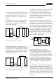
Product description 1 Product description 1.1 Application 1.2 Configuration With VEGACOM 557 an efficient interface converter (Gateway) is available. It is used for VEGA specific protocols of the DISBUS and LOGBUS into standard data formats. The component VEGACOM 557 is designed in 19" technology with 5 TE width (1 TE = 5.08 mm) acc. to DIN 41 494. It can be used: - in carrier BGT 596 - in VEGALOG 571 carrier BGT LOG 571 - in housing type 505.
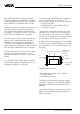
Product description 1.3 Function Communication process DISBUS The data communication between VEGACOM 557 and the communication processor CP 524/525 is only made if initiated by the PLC which can call up the requested information via special commands. The data from DISBUS/LOGBUS are first written in a buffer memory in VEGACOM 557. The new generation of VEGAMET 500 signal conditioning instruments can transfer measured data and status information via the DISBUS to VEGADIS 174 indicating instruments.
Product description 1.
Product description 1.5 Technical data Power supply Operating voltage Power consumption Fuse Galvanic separation Unom = 24 V AC (20 … 53 V), 50/60 Hz or = 24 V DC (20 … 72 V) approx. 6 VA or approx. 4 W 1 A, slow-blow up to 4 kV Meas. data input DISBUS Data transmission Connection cable Cable length Galvanic separation DISBUS (digital data transmission) 2-wire unscreened (standard cable) max. 1000 m up to 0.5 kV Meas.
Product description Indicating elements LED in front plate - green "BA" - red (flashing) - red (on) - green "on" signal for active communication via 3964/3964 R DISBUS/LOGBUS failure failure operating condition Ambient conditions Permissible ambient temperature Storage and transport temperature Moisture Shock load -20°C … +60°C -20°C … +85°C 93 %, T = 40°C acc. to DIN/IEC 68-2-3 2 … 100 Hz, 0.
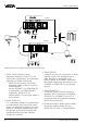
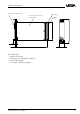
Product description 1.6 Dimensions front RS 232C interface (PC) Multiple plug 5 TE 128,4 LOGBUS plug 100 Circuit board 100 x 160 x 1.
Mounting and electrical connection 2 Mounting and electrical connection 2.1 Mounting instructions The gateway VEGACOM 557 can process measured data and status information in two different ways: - via DISBUS (from measuring systems with VEGAMET) - via LOGBUS (from measuring systems with VEGALOG). Instrument coding Function coding VEGACOM 557 a27 c3/c11 Instrument coding Function coding d b z a c 1 For DISBUS configurations, VEGACOM 557 can be either mounted into carrier BGT 596 or housing type 505.
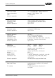
Mounting and electrical connection 2.2 Potential stages and galvanic separation P1 … P4: Potential stages P1 4 RS 232C P2 Power supply unit Microcontroller Field bus controller DISBUS / LOGBUS P4 Siemens S5 P3 2 2/5 3…5 2.
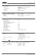
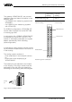
Addressing of the process signals 3 Addressing of the process signals 3.1 Switch adjustments on VEGACOM 557 DIL switch basic board even parity ON For adjustment of the RS 232 PC interface in the front panel, a 6-pole DIL switch block is located on the basic board. On the additional board there are three 6-pole DIL switch blocks as well as two hook switches which are used for configuration of the interface to CP524/525. no parity EDG 1 2 3 4 5 6 1. instrument 2.
Addressing of the process signals Additional board bottom view: DIL switch 1 additional board DIL switch Selection of the interface 1 2 3 SW 8 SW 7 SW 6 ON OFF OFF RS 232 OFF ON OFF RS 422, RS 485 OFF OFF ON TTY LR LR Bus termination for RS 485, RS 422 2 1 Hook switch SW 5 SW4 ON ON bus termination ON OFF OFF bus termination OFF Top view to the removed additional board Selection of the protocol SW 3 SW 2 SW 1 OFF OFF OFF free The hook switches enable the selection be
Addressing of the process signals DIL switch 2 additional board DIL switch 3 additional board (negligible) Selection of the baud rate OFF 300 Baud ON OFF OFF 600 Baud OFF ON OFF 1200 Baud ON ON OFF 2400 Baud OFF OFF ON 4800 Baud ON OFF ON 9600 Baud OFF ON ON 19200 Baud ON ON ON 38400 Baud DIL switch 1 DIL switch 2 EPG ON OFF setting) Siemens 3964 R 9600 baud 8 even RS 232 DIL switch 3 1 2 3 4 5 6 7 8 OFF Switch position (factory Procedure Data transmission Number of d
Addressing of the process signals V24 module RS 485 (module RS422/485) The factory setting of the 8 bridges is 1 - 2, except bridge Br4 (2 - 3). The mode half duplex must be set on the RS 422/485 module. CP 524 COM 557 RxD 3 TxD 2 d18 RxD GND 7 d16 GND z18 TxD DIL switch 1 on VEGACOM additional board: SW 8: ON; SW 7: OFF; SW 6: OFF. Activate the RS 232 interface with the hook switch on the additional board. RS 422 (module RS422/485) The mode full duplex must be set on the RS 422/485 module.
Setup 4 Setup 4.1 Check list The check list gives a short overview on the activities required for configuration. A detailed description of the individual items is made in this document. • Equip VEGACOM 557 with the additional board S5 (for communication with procedure 3964 /R). • Equip communication processor CP with the necessary interface (RS232, RS422/485 or TTY). Set interface number • Adjust VEGACOM DIL switches and hook switches. Interface parameters must be adjusted.
Setup Basic pattern To create a new program, you have to enter the file and system name in the basic pattern. As component, you have to choose RK (for computer link). BASIC PATTERN –> P R O G R A M C H O I C E F1 CHOICE | | | F2 | | | SIMATIC S5 / COM 525 DRIVE: PROGRAM NAME: COMPONENTE: C PROGR 1 RK System name: Creator: Creation date: system tgr 03.11.94 PG Datue - Time: T M J H M 08.11.
Setup Order indicating values After F1 selection (see previous pattern) the adjustment of the order number is expected, here e.g. 1. For parameter setting of order number 1, function key F5 (Order Progr.) must be selected: In this pattern it will be determined that order no. 1 is a Fetch order (fetch data). The data to be received should be fetched by source data component 3 from source word address 0. Coordination markers are not required. -> CHOICE -> ORDER BLOCK -> O R D E R P R O G R .
Setup Order switching condition relay The relays are saved in data component DB5. Therefore it is necessary to enter this data component in the order. The order number has been set to 2 as we assumed that already an order for reading the measured values is available. -> CHOICE -> ORDER BLOCK -> O R D E R P R O G R .
Setup Select with F7 in the field program name the program library COMLIB02. Push F4 to select the procedure: -> PROGRAM CHOICE -> CHOICE-> TRANSMIT –> P R O C E D U R E ————————————————————————————————————— VOLUME: DRIVE: INTERFACE NO.
Setup Select with F7 in the field program name the programming library COMLIB02. For interpreter selection push F3: -> PROGRAM CHOICE -> CHOICE-> TRANSMIT –> P R O C E D U R E ————————————————————————————————————— VOLUME: DRIVE: INTERFACE NO.
S5 functional component 5 S5 functional component For the STEP 5 user program, internal functional components (HTB handling components) HTB SYNCHRON, HTB FETCH and HTB RECEIVE are required. To call up the internal function components, these must be loaded first from the automation device AG S5. The menu selection is then as follows: Object > Components > Transfer > AG file. 5.1 Synchron order After the starting-up phase, the CP expects a SYNCHRON order.
S5 functional component 5.2 Handling components for reading in of data (indicating values) For reading in the indicating values from the VEGAMET instruments and saving them in a PLC data component, the handling component HTB FETCH is necessary to place orders and the HTB RECEIVE to fetch and save data. Handling component FETCH The FETCH component gives the order to the CP to fetch data of a communication partner. The receipt of the data however is carried out by the component RECEIVE.
S5 functional component Handling component RECEIVE This component receives the data of the stated order number. Difference is made between the two function modes: • RECEIVE -All data can be received for each individual order.
S5 functional component 5.3 Reading in data (indicating values) The indicating values are saved in a PLC data component of the S5 data memory. It is obligatory to state DB3 in the programming package COM 525 when determining the orders for measurement loops 1 … 128 and DB4 for measurement loops 129 … 255. See also chapter 5.1. Here also the data destination, e.g. source data component 3 from source word address 0 is stated.
S5 functional component Status values: STAT Meaning 00 H Valid value 01 H Simulated value 80 H Value not available FF H General error Calculation of the data word address The data word address of the first indicating value of VEGAMET to address is determined as follows: Data word address = VEGAMET address • 14 + ZANF (Fetch) for the parameter ZANF from Fetch order ZANF (Fetch) = 0 results from: VEGAMET (DISBUS): Data word address = VEGAMET address • 14 – Source word address • 2 for VEGAMET address
S5 functional component Saving of VEGALOG data in a PLC data component 2 data words (4 bytes) are required per indicating value. These are saved in the PLC data component DB as follows: Image 2 VEGALOG functional component no. = 1 … 254 (source word address 0) DW 0 HB LB ME STAT VEGALOG functional component no. 1 2 HB LB ME STAT VEGALOG functional component no. 2 4 HB LB ME STAT VEGALOG functional component no.
S5 functional component Saving of the relay information from VEGALOG out of data component 1 data word will be reserved per LOGBUS card. In total, 32 data words will be covered by VEGALOG. DW Card address 0 1 1 2 2 3 3 4 4 5 … … 31 32 Contents of the data words: Bits 15 14 13 12 11 10 9 8 7 6 5 4 3 2 1 0 Status reser- reser- reser- reser- reser- Relay Relay Relay Relay Relay Relay Relay Relay Relay Rel.
S5 functional component Parameter setting of the RECEIVE component The information on the data destination, parameter : ZTYP, DBNR, ZANF and ZLAE are irrelevant as this information was already defined in the programming package COM 525 with the order determination. SSNR: A-NR: ANW: ZTYP: DBNR: ZANF: ZLAE: PAFE: The interface number corresponds to the switch positions in the CP.
S5 functional component Call up of the Fetch and Receive component for the indicating values The program reads in the indicating values for the VEGAMET instruments (DISBUS) or VEGALOG instruments (LOGBUS). The Fetch order was determined in the programming package COM 525 with order number 1. The statements on the data destination had been carried out in the programming package with the order determination.
S5 functional component Call up of the Fetch and Receive component for the relay information ... FB 2 Network 1 Name :REL Name SSNR A-NR ANZW ZTYP DBNR ZANF ZLAE PAFE Name SSNR A-NR ANZW ZTYP DBNR ZANF ZLAE PAFE C:CP524_ST.S5D 0000 :O M 1.1 :ON M 1.1 : : :SPA FB 246 :FETCH : KY 0,0 : KY 0,2 : MW 11 : KC DB : KY 0,4 : KF +0 : KF +32 : MB 4 : : : : : : : :O M 1.1 :ON M 1.
S5 functional component Saving of the VEGAMET data in the PLC data component Data word DW 0 00 00 00 80 2 00 00 00 80 12 00 00 00 80 14 HB LB ME STAT 16 HB LB ME STAT 18 HB LB ME STAT 20 HB LB ME STAT 22 HB LB ME STAT 24 HB LB ME STAT 7 pieces reserved, are not used 7 pieces VEGAMET address 1 7 pieces VEGAMET address 2 up to 40 Saving of the VEGALOG data into PLC data component Data word DW 0 HB LB ME STAT DCS 1 2 HB LB ME STAT DCS 2 4 HB LB ME
Supplement 6 Supplement 6.1 Short description of the standard interfaces RS 232, RS 422 and RS 485 Hardware handshake: The receiver controls via its handshake outputs DTR or DSR the handshake inputs CTS or DSR of the emitter. The standard interfaces RS 232, RS 422, RS 485 used in VEGACOM 557 depending on the version, transmit the data serially and asynchronously in bit form. Thereby the conditions "0" and "1" are transmitted by defined voltage levels.
Supplement The interface RS 422 transfers the data as voltage difference between two corresponding cables. Signal earth as grounding is not required. One pair of wires is required for the transmitting as well as for the receipt signal, consisting of an inverted and a non-inverted signal cable. Possible common-mode interferences cause a symmetric shift of the voltage level and cannot deteriorate the useful signal.
Supplement Table: Comparison of important interface data Interfaces Transmission Number of drivers Number of receivers Transmission distance max. transmission rate asym. 1 1 15 m 20 KBit/s RS 232 C symmetr. 1 10 1200 m 10 MBit/s RS 422 A symmetr. 32 32 1200 m 10 MBit/s Emitter Permissible driver output voltage Driver output signal - without load - with load Driver load ±25 V –0.25…6 V –7…12 V ±15 V ±5V 3…7 kOhm ±5V ±2V 100 Ohm ±5V ±1.
Supplement 6.2 Complete overview on process image of measured values in VEGACOM Data component in VEGACOM 36 Data word VEGALOG in VEGACOM Sorting acc. to VEGAMET addresses VEGAMET VEGAMET 513 509, 512 514, 515, 614 Sorting acc.
Supplement Data component in VEGACOM Data word in VEGACOM DB3 DW 88 DB3 DW 90 DB3 VEGALOG Sorting acc. to VEGAMET addresses Sorting acc.
Supplement VEGALOG Sorting acc.
Supplement Data component in VEGACOM Data word VEGALOG in VEGACOM DB4 DW 12 DCS 135 - - - - DB4 DW 14 DCS 136 - - - - DB4 DW 16 DCS 137 - - - - DB4 DW 18 DCS 138 - - - - DB4 DW 20 DCS 139 - - - - DB4 DW 22 DCS 140 - - - - Sorting acc. to VEGAMET addresses VEGAMET VEGAMET 513 509, 512 514, 515, 614 Sorting acc.
Supplement VEGALOG Sorting acc.
Supplement Data word VEGALOG Sorting acc. to VEGAMET addresses VEGAMET VEGAMET 513 509, 512 514, 515, 614 Sorting acc.
Notes 42 VEGACOM 557 Siemens
Notes VEGACOM 557 Siemens 43
VEGA Grieshaber KG Am Hohenstein 113 77761 Schiltach/Germany Phone +49 (0) 7836 50-0 Fax +49 (0) 7836 50-201 E-Mail info@de.vega.com www.vega.com ISO 9001 All statements concerning scope of delivery, application, practical use and operating conditions of the sensors and processing systems correspond to the latest information at the time of printing. Technical data subject to alterations 2.