
Manual

VEGACOM 557 Modbus 33
010001
110002
210003
310004
410005
510006
610007
710008
810009
910010
1010011
50910510
51010511
51110512
1110012
1210013
1310014
1410015
1510016
1610017
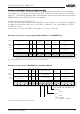
1 BIT
Register
address
in
Modicon
Output 9
Values of
VEGALOG
Card on
module
= 1
Register
address in
VEGA-
COM 557
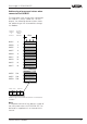
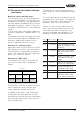
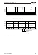
Addressing of the switching status in VEGACOM 557
on VEGALOG 571
Output 10
reserved
reserved
reserved
reserved
reserved
Status: Card
Output 1
Output 2
Output 3
Output 4
Output 5
Output 6
Output 7
Output 8
Output 9
Output 6
Output 7
Output 8
Values of
VEGALOG
Card on
module
= 32
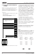
Status of
output card
Switching status of output no:
Data image in VEGACOM 557
Addressing of the output status when
connected to LOGBUS
The image of the output status when con-
nected to VEGALOG is always sorted acc. to
the module numbers of the output cards. The
following demonstration shows the address-
ing of the intermediate storage via Modbus.
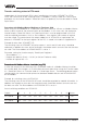
Imagining the 16 register bits belonging to a
module cards as a 16 bit word, the following
regulation results.
The meaning of the individual bits is defined
as follows:
Status of the output card:
0 = OK
1 = no values of the output card available
(no outputs configured or card not
available)
Switching status of the outputs on AR or AT
cards:
0 = relay deenergised
1 = relay energised
Note:
A complete overview of the process image of
the switching status of VEGACOM 557 can
be found in supplement B at the end of this
manual.
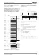
0123
123
4567
4567
01234567Bit
1.
Byte
2.
Byte
8910