
Manual

VEGACOM 557 Modbus 29
010001
110002
210003
310004
410005
510006
610007
710008
810009
910010
1010011
23710238
23810239
23910240
1110012
1210013
1310014
1410015
1510016
1610017
1710018
1810019
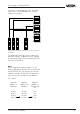
1 BIT
eeee
Register
address
in
Modicon
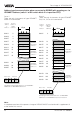
Input contact 2
VEGAMET
with
DISBUS
address =
1
Register
address in
VEGA-
COM 557
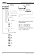
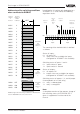
Addressing of the switching conditions in VEGACOM
557 on VEGAMET 513, 514, 515 or 614
Input contact 1
reserved
reserved
reserved
reserved
reserved
Status: Inputs
Relay contact 1
Relay contact 2
Fail safe relay
reserved
reserved
reserved
reserved
Status: Outputs
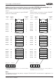
Input contact 2
Input contact 1
reserved
VEGAMET
with
DISBUS
address =
2
VEGAMET
with
DISBUS
address =
15
reserved
reserved
Status: Outputs
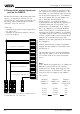
Status of
inputs
Switch-
ing
status of
input
no.:
Status of
outputs
Switching
status of
output no.:
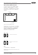
Data image in VEGACOM 557
Addressing of the switching conditions
when connected to DISBUS
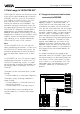
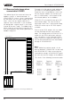
Imagining the 16 register bits belonging to a
VEGAMET as a 16 bit word, the following
regulation results.
The meaning of the individual bits is defined
as follows:
Status of inputs:
0 = all inputs OK
1 = input status not available (no inputs
configured or VEGAMET not available)
Switching status of inputs 1 and 2:
0 = input contact is open
1 = input contact is closed
Status of outputs:
0 = all outputs OK
1 = output status not available (no outputs
configured or VEGAMET not available)
Switching status of outputs 1, 2 and 3 (output
3 corresponds to fail safe relay):
0 = relay is deenergised
1 = relay is energised
Note:
A complete overview of the process image of
the switching status of VEGACOM 557 is
given in supplement B at the end of this
manual.
0123
123
456701234567Bit
12
1.
Byte
2.
Byte