
Manual


18 VEGACOM 557 Modbus
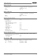
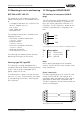
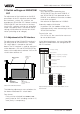
Pin assignments VEGACOM 557AP
Pin-Nr. RS 232 RS422 RS485 TTY
1
----
2 RXD RX
-
T+
3 TXD TX DATA R+
4
----
5 GND GND GND GND
6 - - +5V -
7-/RX-T-
8 - /TX /DATA R-
9-- --
9-pole SUB-D-plug
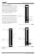
Pin-Nr. RS 232 RS422 RS485 TTY
1
----
2 TXD RX
-
T+
3 RXD TX DATA R+
4
----
5 GND GND GND GND
6 - - +5V -
7-
/RX
-
T-
8-
/TX /DATA R-
9-- --
9-pole SUB-D-socket
Mounting and electrical connection
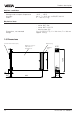
Mounting instructions for VEGACOM
557AP
The two modules connected to the back-
panel print consist of:
- two multipoint connector acc. to DIN 41
612, series F, 48-pole (d, b, z) connected
via the back-panel print
- four screws
- six coded pins
- four guide rails
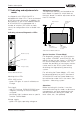
Coding
The coding should be carried out for both
modules as described in chapter “2.1 Mount-
ing in carrier and housing“.
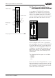
Module position
BGT LOG 571
The module position is individually selectable,
the VEGALOG 571 processing system
adapts automatically through
autoconfiguration during the first booting.
After autoconfiguration, the slot location of the
cards must never be changed.
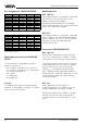
BGT 596
The module position is individually selectable.
Please note that the two connected modules
cover a width of 10 TE (5 TE for VEGACOM
557 plus 5 TE for the adapter board
VEGACOM 557AP).
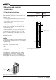
Connection VEGACOM 557AP
BGT LOG 571
With the bus board (part of the carrier BGT
LOG 571) connection to LOGBUS is made
automatically when inserting VEGACOM 557.
The voltage supply of the card must be pro-
vided separately. For this reason, a 2-pole
terminal with tension spring connection,
called U
b,
is available on the back-panel
print. The permissible operating voltage of
VEGACOM 557 should be observed. In case
of DC voltage supply, the correct polarity
should be noted!
BGT 596
When operating VEGACOM 557 as
DISBUS participant, the DISBUS must be
wired in addition to the supply voltage.
For the two cables of the DISBUS, a 2-pole
terminal with tension spring connection is
available. Make sure that the polarity is cor-
rect!