Level and Pressure Operating Instructions VEGACOM 557 Modbus protocol PC BA on 557 in out
Contents Contents Safety information ........................................................................ 3 Note Ex area ................................................................................ 3 1 Product description 1.1 Application ............................................................................ 4 1.2 Configuration ........................................................................ 4 1.3 Functions ..............................................................................
Contents 5 Setup 5.1 Setup check list: ................................................................. 34 5.2 Communication structure ................................................... 34 5.3 Format for the transfer of measured values .................... 35 5.4 Data transmission with Modbus RTU ............................... 36 5.5 Data transmission with Modbus ASCII ............................ 43 Supplement A .................................................................................
Product description 1 Product description 1.1 Application 1.2 Configuration The VEGACOM 557 is an efficient and easyto-use interface converter (Gateway) for your measurement applications. It is used for conversion of the VEGA-specific protocols of DISBUS and LOGBUS into standard data formats. The component VEGACOM 557 is designed in 19" technology with 5 TE width (1 TE = 5.08 mm) acc. to DIN 41 494. It can be used: - in carrier BGT 596 - in VEGALOG 571 carrier BGT LOG 571 - in housing type 505.
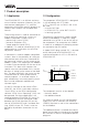
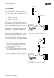
Product description VEGAMET 1.3 Functions DISBUS % 100 The VEGACOM 557 interface converter can be integrated into the VEGA level or pressure measuring system in two different ways: + - ESC OK CONNECT ! on VEGAMET 513 VEGACOM 557 either - as DISBUS participant or - as LOGBUS participant. PC BA ! on VEGACOM 557 In both cases, VEGACOM 557 operates as passive participant and provides measured data and status information of the connected VEGA signal conditioning instruments via the Modbus.
Product description VEGACOM 557 on DISBUS VEGAMET series 500/600 signal conditioning instruments transmit via the DISBUS cyclically measured data and status information, so called PC/DCS telegrams. VEGACOM 557 receives as participant on the DISBUS these data and makes them available (in buffer memory) for collection via the Profibus DP. VEGACOM 557 on LOGBUS Data are exchanged continuously on the LOGBUS between the individual components of VEGALOG 571.
Product description VEGACOM 557 on Modbus The data communication between VEGACOM 557 and Modbus master is only carried out if initiated by the master, which can enquire the requested information by means of special commands. The data from DISBUS/LOGBUS are first written in a buffer memory of VEGACOM 557. The data set is transferred from this buffer memory into a process image. The protocol conversion software enquires the stored data cyclically from the individual storage areas.
Product description Complete measuring system with digital communication and networking DISBUS on % 100 % 100 % 100 % 100 % 100 % 100 % 100 % 100 - + - + - + - + - + - + - + - + ESC OK ESC OK ESC OK ESC OK ESC OK ESC OK ESC OK ESC OK CONNECT ! CONNECT ! on 513 CONNECT ! on VEGAMET 513 CONNECT ! on VEGAMET VEGAMET 513 CONNECT ! on on VEGAMET 513 CONNECT ! on VEGAMET 513 CONNECT ! on VEGAMET 513 CONNECT ! on VEGAMET VEGAMET 513 513 M
Product description 1.4 Type plate Type plate Before mounting and electrical connection, please check if you are using the correct version of VEGACOM 557. Please note the type plate, located below the multiple plug. Type plate on multiple plug The type plate contains important data required for electrical connection. The configuration and the components of the type plate are explained in the illustration below. Note: The serial number of your VEGACOM is on the rear of the plug connector.
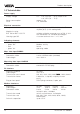
Product description 1.5 Technical data Power supply Supply voltage Power consumption Fuse Unom = 24 V AC (20 … 53 V), 50/60 Hz or = 24 V DC (20 … 72 V) approx. 6 VA 1 A, slow-blow Electrical connection Component Module in carrier BGT 596 or BGT LOG 571 Housing type 505 multiple plug acc. to DIN 41 612, series F 48 pole (d, b, z) with coding holes suitable multipoint connector acc. to DIN 41 612 with connection via standard technologies via screw terminals max. 1 x 1.
Product description Modbus RTU-mode Coding system Number of bits Parity Backup 8 bits binary, hexadecimal 1 start bit, 8 data bits, 1 (0) parity bit, 1 stop bit NONE, ODD, EVEN CRC - 16 Modbus ASCII-mode Coding system Number of bits Parity Backup hexadecimal, ASCII-character 1 start bit, 8 (7) data bits, 1 (0) parity bit, 1 stop bit NONE, ODD, EVEN LRC Electrical protective measures Protection: not mounted in carrier BGT 596 or BGT LOG 571 - front side completely equipped - upper and lower side BGT 596
Product description Ambient conditions Permissible ambient temperature Storage and transport temperature Humidity Shock -20°C … +60°C -20°C … +85°C 93 %, T = 40°C acc. to DIN/IEC 68-2-3 2 … 100 Hz, 0.7 g Mechanical data Series module unit for - carrier BGT 596 - carrier BGT LOG 571 - housing type 505 W = 25.4 mm (5 TE), H = 128.4 mm, D = 166 mm approx. 550 g Dimensions, not mounted Weight 1.
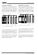
Product description 1.7 Indicating and adjustment elements As diagnostic aid, VEGACOM 557 is equipped with three LEDs. These are located on the instrument front panel. In addition, the basic board, as well as the additional board of VEGACOM 557 are equipped with a number of switches (DIP switch or hook switch) for configuration of the available interfaces. Adjustment elements The adjustment elements are located on the basic board.
Mounting and electrical connection 2 Mounting and electrical connection 2.1 Mounting instructions The gateway VEGACOM 557 can process measured data and status information in two different ways: - via DISBUS (from measuring systems with VEGAMET) - via LOGBUS (from measuring systems with VEGALOG). Instrument coding VEGACOM 557 a27 c3/c11 Instrument coding Function coding d b z a c 1 For DISBUS configurations, VEGACOM 557 can be either mounted into carrier BGT 596 or housing type 505.
Mounting and electrical connection 2.2 Mounting in carrier and housing 2.3 Wiring plan VEGACOM 557 BGT 596 or BGT LOG 571 PC interface in front panel (SUB-Dplug) For mounting, a slot module must be provided at the location. A slot module consists of: - a multipoint connector acc. to DIN 41 612, series F, 33-pole (d, b, z) - two screws - three coded pins - two guide rails. The multipoint connector is available in the following versions: - Wire-Wrap, standard connection 1.0 mm x 1.
Mounting and electrical connection Connection via modem For remote parameter adjustment, it is possible to connect the PC interface via a modem. In such a case, the modem cable that comes with the respective modem should be used. Modem operation is supported by VEGACOM 557 from software version 2.11. Further information on the remote parameter adjustment is stated in the operating instructions "Remote parameter adjustment“.
Mounting and electrical connection Supply voltage – 2.4 Mounting and installation instructions with VEGACOM 557AP d b z + 2 4 6 8 10 12 Modbus via TTY 14 16 18 20 DISBUS (not + used on VEGA– LOG) GND T+ R- As an option, VEGACOM 557 can be extended with the adapter print VEGACOM 557AP. The adapter print VEGACOM 557AP consists of a module card with 5 TE width and two modules connected to a back-panel print for carrier BGT 596 or BGT LOG 571.
Mounting and electrical connection Pin assignments VEGACOM 557AP Pin-Nr. 1 2 3 4 5 6 7 8 9 RS 232 RXD TXD GND - RS422 RX TX GND /RX /TX - RS485 DATA GND +5V /DATA - TTY T+ R+ GND TR- RS422 RX TX GND /RX /TX - RS485 DATA GND +5V /DATA - TTY T+ R+ GND TR- Module position BGT LOG 571 The module position is individually selectable, the VEGALOG 571 processing system adapts automatically through autoconfiguration during the first booting.
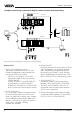
Mounting and electrical connection Terminals for supply voltage Ub+ Terminals for DISBUS View of back-panel board (rear of the carrier) Modbus interface of VEGACOM 557 as SUB-D-plug PC interface of VEGACOM 557 PC Modbus interface of VEGACOM 557 as SUB-D-socket BA on 557 557AP Front view with SUB-D-connections of VEGACOM 557 and VEGACOM 557AP VEGACOM 557 Modbus 19
Switch adjustments on VEGACOM 557 3 Switch settings on VEGACOM 557 For adjustment of the interfaces or the BUS parameters of the PC interface and the Modbus interfaces, various DIL switches are provided on VEGACOM 557. Before inserting VEGACOM 557 into the carrier or the housing, the DIL switches must be set according to the user-specific data. The data of these settings will be effective with the next initialization (switching on of voltage). 3.
Switch adjustments on VEGACOM 557 DIL switch block 1 (additional board) 3.2 Adjustment of the Modbus interface DIL switch blocks additional board Additional board 1 2 3 Hook switches additional board 2 1 1 2 3 4 5 6 7 8 ON Three 8-pole DIL switch blocks as well as two hook switches for configuration of the Modbus interface to the DCS or the PLC are located on the additional board.
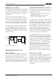
Switch adjustments on VEGACOM 557 DIL switch block 2 (additional board) DIL switch block 3 (additional board) Factory setting 1 2 3 4 5 6 7 8 ON 1 2 3 4 5 6 7 8 ON Factory setting DCS measured value image (only relevant on VEGAMETs) all meas. values Met 1, all meas. values Met 2, etc. 1. meas. value Met 1, 1. meas. value Met 2, etc. Protocol mode Modbus ASCII Modbus RTU Parity Modbus address of VEGACOM 557 (Adr. 001 to 246) e.g.: Adr.
Switch adjustments on VEGACOM 557 Hook switches (additional board) The hook switches on the additional board enable the selection between TTY and RS 232 interface. The additional print has to be removed from the basic print to modify the settings. DIL-switch 1 2 3 LR LR 2 1 Hook switches View to the removed additional print Depending on the requirements, the Modbus interface can be used as TTY interface but also as RS 232 interface (using the hook switches).
Data image in VEGACOM 557 4 Data image in VEGACOM 557 VEGACOM 557 collects the measured values of the VEGA signal conditioning instruments VEGAMET 509, 512, 513, 514, 515 and 614 (via DISBUS) or VEGALOG 571 (via LOGBUS) and puts them in the temporary memory for collection via the Modbus. The method of storing the measured values (for the higher-priority processing system) in the VEGACOM 557 temporary memory differs depending on the selected configuration.
Data image in VEGACOM 557 If switch 1 is set to position "ON“, the measured values will be grouped acc. to DCS indices or channels. all DCS outputs with index =1 all DCS outputs with index =2 % 100 % 100 % 100 % 100 - + - + - + - + ESC OK ESC OK ESC OK ESC OK CONNECT CONNECT ! CONNECT ! on ! on VEGAMET 513 CONNECT ! on VEGAMET on VEGAMET 513 VEGAMET 513 513 Grouping of measured values acc.
Data image in VEGACOM 557 Addressing of measured value when connected to DISBUS with grouping acc. to VEGAMET address (switch 1 of DIL switch block 2 is in position OFF): Case 1: There are only instruments of type VEGAMET 509 or 512 connected. Register address in VEGACOM 557 4 Byte 30001 0 reserved 30003 2 reserved 30005 4 reserved 30007 6 Meas. value channel 1 Register address in Modicon 30009 8 30011 10 Meas. value channel 2 Meas. value channel 3 30013 12 Meas.
Data image in VEGACOM 557 Addressing of measured value when connected to DISBUS with grouping acc. to DCS indices (switch 1 of DIL switch block 2 is in position ON): Case 1: There are only instruments of type VEGAMET 509 or 512 connected. Register address in Modicon Register address in VEGACOM 557 4 Byte VEGAMET with DISBUS address = Case 2: There are only instruments of type VEGAMET 513, 514, 515 or 614 connected.
Data image in VEGACOM 557 4.2 Image of the contact inputs/outputs on the DISBUS Beside the previously described measured values, it is possible to transmit via the VEGACOM 557 also switching conditions of the VEGA signal conditioning instruments VEGAMET 513, 514 and 515. These are: - condition of the contact inputs (position of key switch etc.
Data image in VEGACOM 557 Addressing of the switching conditions when connected to DISBUS Register address in Modicon Register address in VEGACOM 557 1 BIT 10001 0 Input contact 2 10002 eeee 10003 1 Input contact 1 2 reserved 10004 3 reserved 10005 4 reserved 10006 5 reserved 10007 6 reserved 10008 7 Status: Inputs 10009 8 Relay contact 1 10010 9 Relay contact 2 10011 10 Fail safe relay 10012 11 reserved 10013 12 reserved 10014 13 reserved 10015 14 reserved 10
Data image in VEGACOM 557 4.3 Measured value image when connected to LOGBUS The addressing of the measured values for Modbus systems is "word orientated“. In VEGACOM 557 a meas. value is represented by two words, the first word includes the real meas. value, the next higher word the respective status information. In the standard, the designation “register word” is also used instead of the term “word”. The addressing is either made via existing library enquiries of a PLC (e.g.
Data image in VEGACOM 557 Addressing of measured values when connected to LOGBUS The measured value image when connected to LOGBUS is always sorted acc. to DCS outputs; the following demonstration shows the addressing of the intermediate storage via Modbus.
Data image in VEGACOM 557 4.4 Image of the contact outputs on LOGBUS Beside the previously described measured values, it is also possible to transmit the switching status of VEGA processing system VEGALOG 571 through VEGACOM 557.
Data image in VEGACOM 557 Addressing of the output status when connected to LOGBUS The image of the output status when connected to VEGALOG is always sorted acc. to the module numbers of the output cards. The following demonstration shows the addressing of the intermediate storage via Modbus. Register address in Modicon Register address in VEGACOM 557 Imagining the 16 register bits belonging to a module cards as a 16 bit word, the following regulation results.
Setup of VEGACOM 557 5 Setup 5.1 Setup check list: Proceed with the setup of VEGACOM 557 on Modbus as follows: I. Check hardware requirements: • Modbus-compatible Master component (Modus: RTU or ASCII) • Check interface type (RS 232, RS 485, RS 422 or TTY) • VEGACOM 557 version "Modbus“ II. Carry out adjustments on VEGACOM 557 (DIL switch on additional board): • Adjust mode for Modbus • Activate interface type • Set parameter for interface • Set Modbus address III.
Format for the transfer of measured values 5.3 Format for the transfer of measured values Measured values and DCS values The measured values of the VEGA processing systems (VEGAMET or VEGALOG) connected to VEGACOM 557 are reproduced at the input registers of Modicon 584 in the way described in chapter 4.1 and 4.3. They are available in VEGACOM 557 as so called DCS values. A DCS value covers two register addresses, it consists therefore of 2 double words, i.e. 4 Byte.
Data transmission with Modbus RTU 5.4 Data transmission with Modbus RTU Already several years ago, the firm AEG developed a communication technique for its PLC, called Modbus. This specification is used today by several companies for the coupling of IOcomponents. For the Modbus, we distinguish between two versions: Modbus RTU and Modbus ASCII. Both have the same data content, but the scale and the coding of the characters are different. RTU mode With the RTU coding, the message starts with a break of 3.
Data transmission with Modbus RTU Procedure with Modbus-Master-simulation (e.g. PC) In case the data enquiry should be made via a Modbus-Master-simulation, this can be done, for example, via a self-written communication driver using the "Function code 04 = Read Input Registers“. The following demonstration should explain the communication processes between Modbus-Master and VEGACOM 557 on the Modbus. Example for data from VEGAMET 514: A DCS value should be collected from VEGAMET #2 (DCS output 1).
Data transmission with Modbus RTU Transfer switching status to RTU mode Independent of the connected VEGA signal conditioning instrument (VEGAMET or VEGALOG), the transmission of the switching status via Modbus is always made acc. to the same procedure via the function code 01 "Read Coil Status“ or optionally via function code 02 "Read Input Status“.
Data transmission with Modbus RTU Structure of the enquiry acc. to switching status from Modbus-Master to VEGACOM 557 Meaning Start Number of Bytes 3 ... 4 Value range Closed level Slave Func- Address of tion 1. register bit address code 1 Number of register bits Error Check End 1 2 2 2 3 ... 4 1 .. 247 01 0 ... 65.509 8 ... 2.040 CRC Closed level 0x01 0x01 0x00 0x20 0x00 0x20 0xXX 0xXX RTU enquiry telegram acc.
Data transmission with Modbus RTU Parameter adjustment of VEGALOG or VEGAMET in RTU mode VEGACOM 557 also provides the option of enquiring and modifying different parameters of the VEGALOG or VEGAMET signal conditioning instruments (relating to measurement loop).
Data transmission with Modbus RTU Diagnostic message in RTU mode Function code 08 (diagnostics) enables the diagnostics of the Modbus-participants through the Modbus-Master. VEGACOM 557 supports the Diagnostic Code 0x0000 (return of the data). In the field "Diagnostic Data“, any approved data can be entered, which are returned unchanged from a functioning VEGACOM 557. Function 08 is implemented in the same manner for both VEGAMET and VEGALOG.
Data transmission with Modbus RTU Error messages in RTU mode Errors in the telegram of function code 04 (Read Input Register) are commented by an error message (Exception Response). The most significant bit of the function code is set to 1 (corresponds to function code + 80H). In the byte Exception Code, the error is named in coded form (see error overview).
Data transmission with Modbus ASCII 5.5 Data transmission with Modbus ASCII Already several years ago, the firm AEG developed a communication technique for its PLC, called Modbus. This specification is used today by several companies for the coupling of IOcomponents. For the Modbus we distinguish between two versions: Modbus RTU and Modbus ASCII. Both have the same data content, but the scale and the coding of the characters are different.
Data transmission with Modbus ASCII Procedure with Modbus-Master-simulation (e.g. PC) In case the data enquiry should be made via a Modbus-Master-simulation, this can be done, for example, via a self-written communication driver using the "Function code 04 = Read Input Registers“. The following demonstration should explain the communication processes between Modbus-Master and VEGACOM 557 on the Modbus. Example for data from VEGAMET 514: A DCS value should be collected from VEGAMET #2 (DCS output 1).
Data transmission with Modbus ASCII Transfer switching conditions in ASCII mode Independent of the connected VEGA signal conditioning instrument (VEGAMET or VEGALOG), the transmission of the switching conditions via the Modbus is always made acc. to the same procedure via the function code 01 "Read Coil Status“ or optionally via function code 02 "Read Input Status“.
Data transmission with Modbus ASCII Structure of enquiry acc. to switching conditions from Modbus master to VEGACOM 557 Meaning Slave address Start Functions code Address of the 1. register bit Number of register bits Error Check End No. of bytes 1 2 2 4 4 2 2 Value range : 1 .. 247 01 0 ... 65.509 8 ... 2.040 LRC CR LF : 0 1 0 1 0 0 2 0 0 0 2 0 X X CR LF ASCII enquiry telegram acc.
Data transmission with Modbus ASCII Parameter setting of VEGALOG or VEGAMET in ASCII mode VEGACOM 557 also provides the option of enquiring and modifying different parameters of the VEGALOG or VEGAMET signal conditioning instruments (relating to measurement loop).
Data transmission with Modbus ASCII Diagnostic message in ASCII mode Function code 08 (diagnostics) enables diagnostics of the Modbus-participants through the Modbus-Master. VEGACOM 557 supports the Diagnostic Code 0x0000 (return of the data). In the field "Diagnostic Data“ any, approved data can be entered, which are returned unchanged from a functioning VEGACOM 557. Function 08 is implemented in the same manner for both VEGAMET and VEGALOG.
Data transmission with Modbus ASCII Error messages in ASCII mode Errors in the telegram of function code 04 (Read Input Register) are commented by an error message (Exception Response). The most significant bit of the function code is set to 1 (corresponds to function code + 80H). In the byte Exception Code, the error is named in coded form (see error overview).
Supplement A Supplement A Complete overview of the process image of measured values in VEGACOM 557: Register w ord address Register w ord address in Modicon im VEGACOM 30.001 0 30.003 2 30.005 4 DCS 3 - - CH1 MET2 DCS1 MET2 30.007 6 DCS 4 MET1 CH1 - CH1 MET3 DCS1 MET3 50 VEGALOG Sorting acc. to VEGAMET addresses Sorting acc.
Supplement A Register w ord Register w ord address address in Modicon in VEGACOM 30.089 88 30.091 90 30.093 VEGALOG Sorting acc. to VEGAMET addresses Sorting acc. to channels / DCS indices VEGAMET 509, 512 VEGAMET 513 514, 515, 614 VEGAMET 509, 512 VEGAMET 513 514, 515, 614 DCS 45 MET14 CH3 MET6 DCS3 CH3 MET14 DCS3 MET12 DCS 46 MET15 CH1 MET6 DCS4 CH3 MET15 DCS3 MET13 92 DCS 47 MET15 CH2 MET6 DCS5 - DCS3 MET14 30.095 94 DCS 48 MET15 CH3 MET6 DCS6 - DCS3 MET15 30.
Supplement A Register w ord Register w ord address address 52 in Modicon in VEGACOM 30.179 178 30.181 180 30.183 30.185 Sorting acc. to VEGAMET addresses VEGALOG Sorting acc. to channels / DCS indices VEGAMET 509, 512 VEGAMET 513, 514, 515, 614 VEGAMET 509, 512 VEGAMET 513 514, 515, 614 DCS 90 - MET12 DCS6 - DCS6 MET9 DCS 91 - MET12 DCS7 - DCS6 MET10 182 DCS 92 - MET13 DCS1 - DCS6 MET11 184 DCS 93 - MET13 DCS2 - DCS6 MET12 30.
Supplement A Register w ord address Register w ord address in Modicon in VEGACOM 30.269 268 30.271 270 30.273 VEGALOG Sorting acc. to VEGAMET addresses Sorting acc. to channels / DCS indices VEGAMET 509, 512 VEGAMET 513 514, 515, 614 VEGAMET 509, 512 VEGAMET 513 514, 515, 614 DCS 135 - - - - DCS 136 - - - - 272 DCS 137 - - - - 30.275 274 DCS 138 - - - - 30.277 276 DCS 139 - - - - 30.279 278 DCS 140 - - - - 30.281 280 DCS 141 - - - - 30.
Supplement A Register w ord Register w ord address address 54 in Modicon in VEGACOM 30.359 358 30.361 360 30.363 Sorting acc. to VEGAMET addresses VEGALOG Sorting acc. to channels / DCS indices VEGAMET 509, 512 VEGAMET 513, 514, 515, 614 VEGAMET 509, 512 VEGAMET 513 514, 515, 614 DCS 180 - - - - DCS 181 - - - - 362 DCS 182 - - - - 30.365 364 DCS 183 - - - - 30.367 366 DCS 184 - - - - 30.369 368 DCS 185 - - - - 30.371 370 DCS 186 - - - - 30.
Supplement A Register w ord Register w ord address address in Modicon in VEGACOM 30.449 448 30.451 450 30.453 VEGALOG Sorting acc. to VEGAMET addresses Sorting acc. to channels / DCS indices VEGAMET 509, 512 VEGAMET 513 514, 515, 614 VEGAMET 509, 512 VEGAMET 513 514, 515, 614 DCS 225 - - - - DCS 226 - - - - 452 DCS 227 - - - - 30.455 454 DCS 228 - - - - 30.457 456 DCS 229 - - - - 30.459 458 DCS 230 - - - - 30.461 460 DCS 231 - - - - 30.
Supplement B Supplement B Register bit address Register bit address in Modicon in VEGACOM 56 Complete overview of the process image of the switching status in VEGACOM 557: VEGALOG Module no. VEGAMET 513, 514, 515, 614 No. of output DISBUS address Status / Sw itching status 10.001 0 #1 Output contact 9 VEGAMET #1 Input contact 2 10.002 1 #1 Output contact 10 VEGAMET #1 Input contact 1 10.003 2 #1 - VEGAMET #1 - 10.004 3 #1 - VEGAMET #1 - 10.
Supplement B VEGALOG Register w ord Register w ord address address VEGAMET 513, 514, 515, 614 in Modicon in VEGACOM Module no. No. of output DISBUS address Status / Sw itching status 10.045 44 #3 Output contact 5 VEGAMET #3 - 10.046 45 #3 Output contact 6 VEGAMET #3 - 10.047 46 #3 Output contact 7 VEGAMET #3 - 10.048 47 #3 Output contact 8 VEGAMET #3 Status of outputs 10.049 48 #4 Output contact 9 VEGAMET #4 Input contact 2 10.
Supplement B VEGALOG Register w ord Register w ord address address 58 VEGAMET 513, 514, 515, 614 in Modicon in VEGACOM Module no. No. of output DISBUS address Status / Sw itching status 10.090 89 #6 Output contact 2 VEGAMET #6 Relay contact 2 10.091 90 #6 Output contact 3 VEGAMET #6 Fail safe relay 10.092 91 #6 Output contact 4 VEGAMET #6 - 10.093 92 #6 Output contact 5 VEGAMET #6 - 10.094 93 #6 Output contact 6 VEGAMET #6 - 10.
Supplement B VEGALOG Register w ord Register w ord address address in Modicon in VEGACOM Module no. VEGAMET 513, 514, 515, 614 No. of output DISBUS address Status / Sw itching status 10.135 134 #9 - VEGAMET #9 - 10.136 135 #9 Status: Card VEGAMET #9 Status of inputs 10.137 136 #9 Output contact 1 VEGAMET #9 Relay contact 1 10.138 137 #9 Output contact 2 VEGAMET #9 Relay contact 2 10.139 138 #9 Output contact 3 VEGAMET #9 Fail safe relay 10.
Supplement B VEGALOG Register w ord Register w ord address address 60 VEGAMET 513, 514, 515, 614 in Modicon in VEGACOM Module no. No. of outputs DISBUS address Status / Sw itching status 10.180 179 #12 - VEGAMET #12 - 10.181 180 #12 - VEGAMET #12 - 10.182 181 #12 - VEGAMET #12 - 10.183 182 #12 - VEGAMET #12 - 10.184 183 #12 Status: Card VEGAMET #12 Status of inputs 10.185 184 #12 Output contact 1 VEGAMET #12 Relay contact 1 10.
Supplement B VEGALOG Register w ord Register w ord address address VEGAMET 513, 514, 515, 614 in Modicon in VEGACOM Module no. 10.225 224 #15 Output contact 9 VEGAMET #15 Input contact 2 10.226 225 #15 Output contact 10 VEGAMET #15 Input contact 1 10.227 226 #15 - VEGAMET #15 - 10.228 227 #15 - VEGAMET #15 - 10.229 228 #15 - VEGAMET #15 - 10.230 229 #15 - VEGAMET #15 - 10.231 230 #15 - VEGAMET #15 - 10.
Supplement B VEGALOG Register w ord Register w ord address address 62 VEGAMET 513, 514, 515, 614 in Modicon in VEGACOM Module no. No. of output DISBUS address Status / Sw itching status 10.270 269 #17 Output contact 6 - - 10.271 270 #17 Output contact 7 - - 10.272 271 #17 Output contact 8 - - 10.273 272 #18 Output contact 9 - - 10.274 273 #18 Output contact 10 - - 10.275 274 #18 - - - 10.276 275 #18 - - - 10.277 276 #18 - - - 10.
Supplement B VEGALOG Register w ord Register w ord address address VEGAMET 513, 514, 515, 614 in Modicon in VEGACOM Module no. No. of output DISBUS address Status / Sw itching status 10.315 314 #20 Output contact 3 - - 10.316 315 #20 Output contact 4 - - 10.317 316 #20 Output contact 5 - - 10.318 317 #20 Output contact 6 - - 10.319 318 #20 Output contact 7 - - 10.320 319 #20 Output contact 8 - - 10.321 320 #21 Output contact 9 - - 10.
Supplement B VEGALOG Register w ord Register w ord address address in Modicon 64 in VEGACOM Module no. VEGAMET 513, 514, 515, 614 No. of output DISBUS address Status / Sw itching status 10.360 359 #23 Status: Card - - 10.361 360 #23 Output contact 1 - - 10.362 361 #23 Output contact 2 - - 10.363 362 #23 Output contact 3 - - 10.364 363 #23 Output contact 4 - - 10.365 364 #23 Output contact 5 - - 10.366 365 #23 Output contact 6 - - 10.
Supplement B VEGALOG Register w ord Register w ord address address VEGAMET 513, 514, 515, 614 in Modicon in VEGACOM Module no. No. of output DISBUS address Status / Sw itching status 10.405 404 #26 - - - 10.406 405 #26 - - - 10.407 406 #26 - - - 10.408 407 #26 Status: Card - - 10.409 408 #26 Output contact 1 - - 10.410 409 #26 Output contact 2 - - 10.411 410 #26 Output contact 3 - - 10.412 411 #26 Output contact 4 - - 10.
Supplement B VEGALOG Register w ord Register w ord address address in Modicon 66 in VEGACOM VEGAMET 513, 514, 515, 614 Module no. No. of output DISBUS address Status / Sw itching status 10.450 449 #29 Output contact 10 - - 10.451 450 #29 - - - 10.452 451 #29 - - - 10.453 452 #29 - - - 10.454 453 #29 - - - 10.455 454 #29 - - - 10.456 455 #29 Status: Card - - 10.457 456 #29 Output contact 1 - - 10.458 457 #29 Output contact 2 - - 10.
Supplement B Register w ord address Register w ord address in Modicon in VEGACOM Module no. No. of output DISBUS address Status / Sw itching status 10.495 494 #31 Output contact 7 - - 10.496 495 #31 Output contact 8 - - 10.497 496 #32 Output contact 9 - - 10.498 497 #32 Output contact 10 - - 10.499 498 #32 - - - 10.500 499 #32 - - - 10.501 500 #32 - - - 10.502 501 #32 - - - 10.503 502 #32 - - - 10.504 503 #32 Status: Card - - 10.
VEGA Grieshaber KG Am Hohenstein 113 77761 Schiltach/Germany Phone +49 (0) 7836 50-0 Fax +49 (0) 7836 50-201 E-Mail info@de.vega.com www.vega.com ISO 9001 The statements on types, application, use and operating conditions of the sensors and processing systems correspond to the latest information at the time of printing.