
User guide


Hardware Installation
692302 3-5
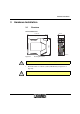
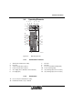
3.2 Operating Elements
Figure 3-3 Operating elements
3.2.1 Connection Terminals
3.2.2 Connectors
P S I - D A T A / F A X - M O D E M / R S 2 3 2
O r d . - N o . 2 7 0 8 2 0 3
V C C
R D
T D
A L R
D T R
D C D
E R R
O H
A A
F A X
E C
L I N E
R E S E T / A L R
6
5
9
7
8
1 0
2
3
1 4
1 5
1 6
1 7
1 3
1 8
2 2
2 1
2 0
1 9
4
1 1
1 2
2 3
2 6
2 5
2 4
6 9 2 3 A 0 3 2
1
1 Shield (telecommunications cable) 7 Not used
2 Not used 8 Not used
3 a (telecommunications cable a) 9 in+ (9 V to 48 V DC switching input)
4 b (telecommunications cable b) 10 in– (0 V switching input)
5 24 V supply (10 V to 60 V DC, 16 V to 40 V AC) 11 out (switching output, form A contact)
6 0 V supply (0 V) 12 out (switching output, form A contact)
13 Line, RJ-12 (telecommunications cable)
18 RS-232 data interface, 9-pos. D-SUB