
Instruction Manual

Connections MoRoS Modem - ISDN 1.3
18
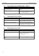
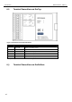
8 CTS Clear To Send
9 RI Ring Indication
Table 11: Description of the pin allocation of the sub-D jack
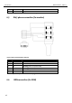
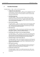
6.5 RJ45 phone connection (for modem)
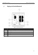
Figure 6: RJ12 jack connected to TAE jack
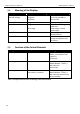
Pin Signal Description
1 E Not connected.
2 a2 To connect a phone in series.
3 a1 Incoming phone line (PSTN or PBX).
4 b1 Incoming phone line (PSTN or PBX).
5 b2 To connect a phone in series.
6 W Not connected.
Table 12: Layout description of the RJ12 and TAE plugs
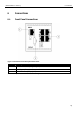
6.6 ISDN connection (for ISDN)
E W
b2 b1
a2 a1