
Instruction Manual

MoRoS Modem - ISDN 1.3 Connections
17
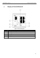
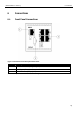
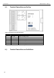
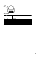
Figure 4: Connections on the bottom of the device
Terminal
Description Description
17 RS 485B Reserved for future applications
18 RS 485A Reserved for future applications
19 GND Ground
20 Input 2 Input 2
21 Input 1 Input 1
22 GND Ground
23 Reset Reset input
24
GND Ground
25 10 ... 60VDC Power supply 10 V – 60 V DC
26 GND Ground
Table 10: Description of the connections on the bottom of the device
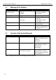
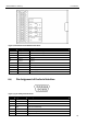
6.4 Pin Assignment of the Serial Interface
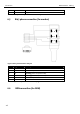
Figure 5: 9-pin sub-D jack at the device
Pin Signal Description
1 DCD Data Carrier Detect
2 RXD Receive Data
3
TXD Transmit Data
4 DTR Data Terminal Ready
5 GND Ground
6 DSR Data set ready
7 RTS Request to send