
Manual


Connections MoRoS GPRS 1.3
18
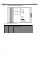
6.4 Pin Assignment of the Serial Interface
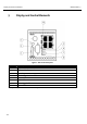
Figure 5: 9-pin Sub-D jack at the device
Pin Signal Description
1 DCD Data Carrier Detect
2 RXD Receive Data
3
TXD Transmit Data
4 DTR Data Terminal Ready
5 GND Ground
6 DSR Data set ready
7 RTS Request to send
8 CTS Clear To Send
9 RI Ring Indication
Table 10: Description of the pin allocation of the Sub-D jack