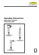
Level and Pressure Operating Instructions Hydrostatic pressure transmitters D81 p
Contents Contents Safety information ........................................................................ 2 Note Ex area ................................................................................ 2 1 Product description 1.1 Function and configuration .................................................. 4 1.2 Electronics version without adjustment .............................. 5 1.3 Electronics version with integrated adjustment in connection housing ...............................................
Contents 3 Electrical connection 3.1 Connection instructions ..................................................... 19 3.2 Terminal assignment .......................................................... 20 3.3 Connection to external connection housing VEGABOX 01 ..................................................................... 21 3.4 Connection examples ........................................................ 22 4 Setup 4.1 Adjustment structure .........................................................
Product description 1 Product description 1.1 Function and configuration Output signal The pressure transmitter D81 is an efficient instrument for hydrostatic level measurement. A dry measuring cell is used as pressure sensor element.
Product description 1.2 Electronics version without adjustment Electronics version A: Pressure transmitter for connection to VEGA signal conditioning instruments VEGAMET VEGALOG e.g. IP 66 VEGABOX 01 Zum Anschluss an For connection to Druckmessumformer mit pressure transmitters with analogem Ausgangssignal analog output 1 2 VEGAMET 10 11 12 3 TRANSMITTER + VEGALOG - - + VEGABOX 01 e.g.
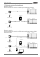
Product description Electronics version I: Pressure transmitter 4 … 20 mA, HART ®, VVO 4-20mA 1 2 3 4 5 + - 4...20mA 12V...36V DC Klemmeinsatz terminal PLC/DCS 250 Ω e.g. IP 66 VEGABOX 01 Zum Anschluss an For connection to 4-20mA Druckmessumformer mit pressure transmitters with analogem Ausgangssignal analog output 1 2 3 4 5 + - 4...20mA 12V...36V DC 1 2 3 TRANSMITTER 10 11 12 + - - + VEGABOX 01 Klemmeinsatz terminal 250 Ω PLC/DCS e.g.
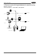
Product description 1.3 Electronics version with integrated adjustment in connection housing Electronics version K: Pressure transmitter 4 … 20 mA, HART ®, VVO adjustable S Z ti Op 1 2 3 4 5 + - 4...20mA 12V...36V DC Bedieneinsatz operating unit PLC/DCS 250 Ω e.g. IP 66 VEGABOX 01 Zum Anschluss an For connection to Druckmessumformer mit pressure transmitters with S Z ti Op analogem Ausgangssignal analog output 1 1 2 3 4 5 + - 4...20mA 12V...
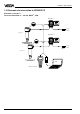
Product description 1.4 Electronics for connection to VEGADIS 12 Electronics version L: Pressure transmitter 4 … 20 mA, HART ®, VVO VEGADIS 12 TRANSMITTER DISPLAY OPERATE ZERO END END For connection to POINT VEGADIS 12 1 1 2 3 4 5 + OPERATE ZERO Zum Anschluß an 2 3 POINT 5 TRANSMITTER 6 7 8 10 + DISPLAY - 11 12 - VEGADIS 12 12V...36V DC Klemmeinsatz terminal 250 Ω PLC/ DCS e.g.
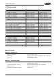
Product description 1.5 Technical data Nominal meas. Range Überdruck 0…0.4 bar / 0…40 kPa 0…1.0 bar / 0…100 kPa 0…2.5 bar / 0…250 kPa 0…5.0 bar / 0…500 kPa 0…10.0 bar / 0…1 000 kPa 0…20.0 bar / 0…2 000 kPa 0…40.0 bar / 0…4 000 kPa 0…60.0 bar / 0…6 000 kPa -0.5…+0.5 bar / -50…+50 kPa -1.0…0.0 bar / -100…0 kPa -1.0…+1.5 bar / -100…+150 kPa -1.0…+4.0 bar / -100…+400 kPa -1.0…+10.0 bar / -100…+1 000 kPa -1.0…+20.0 bar / -100…+2 000 kPa -1.0 …+40.0 bar / -100…+4 000 kPa -1.0…+60.
Product description Weights Pressure transmitter D81 External housing approx. 1.6 … 10 kg (depending on isolating system) approx. 400 g Adjustment and display elements Pressure transmitter - terminal insert - adjustment insert without adjustment elements 2 keys, 1 rotary switch Electrical data Adjustment ranges Zero Span adjustable from -20 … +95 % of nominal range adjustable from 3.
Product description Supply and signal circuit (analogue transmission, 4 … 20 mA), additional data for electronics version L Supply voltage for pressure transmitters in conjunction with VEGADIS 12 - without display 12 … 36 V DC - with display 17 … 36 V DC Max. input current 150 mA Current signal range 3.5 … 22 mA Max.
Product description Protective measures 1) Protection VEGABOX 01 Protection class Overvoltage category IP 66, IP 67, IP 68 IP 66 and IP 67 III III Accuracy (similar to DIN 16 086, DIN V 19 259 - 1 and IEC 770) Deviation Reference conditions (acc.
Product description Operating conditions Ambient conditions Ambient temperature - with display module Storage and transport temperature Medium temperature, depending on isolating liquid - -40°C … +85°C -10°C … +60°C -50°C … +100°C Temperature pabs > 1 bar silicone oil -40°C … +150°C silicone oil and cooling element -40°C … +200°C silicone oil and capillaries 1 m -40°C … +200°C vegetable oil -10°C … +130°C vegetable oil and cooling element -10°C … +200°C high-temperature oil a.
Product description 1.6 Approvals and certificates Approvals - Ex Zone 2 - CENELEC EEx ia IIC - ATEX II 1G EEx ia IIC If the use of approved instruments is required for certain applications, the appropriate official documents (test reports, test certificates and conformity certificates) must be observed. These are supplied with the respective instrument. CE conformity D81 pressure transmitters meet the requirements of EMC (89/336/EWG) and NSR (73/23/EWG). Conformity has been judged acc.
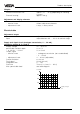
Product description 1.7 Dimensions Housing ø 75 ø 76 ø 41,6 46 ø 41,6 46 67 91 93 ø 41,6 90 63 Process connections D81 Capillaries 1 m Standard Cooling element 51 51 83 100 Standard b f d2 D b k d2 d4 d5 f RL dM d4 RL k D FA, FB, FC FH FN, FO d5 = = = = = = = = = outer flange diameter flange thickness diameter of hole circle diameter of holes seal ledge diameter extension diameter seal ledge strength extension length diaphragm diameter FE, FG, FK Flange connection acc.
Product description Tube isolating diaphragm for mounting between flanges with connection acc. to DIN 2501 PN D Mb RC 50 6 … 400 95 54.5 D DN Mb Order code 60 L2 g DN PN G1 L2 D2 RF 50 25 Rd78x1/6 156 70 d6 g m D2 Order code d6 Tube isolating diaphragm with connection acc. to DIN 11 851 68.5 11 18 Tube isolating diaphragm with Clamp connection L RH 2" 40 156 64 56.
Product description VEGABOX 01 38 72 85 108 118 135 ø 5 M20x1,5 with protective cover Pressure transmitter D81 130 72 139 100 17
Mounting 2 Mounting 2.1 Mounting instructions The pressure transmitter can be mounted in any position. Cable entries must point downwards to avoid moisture ingress. For this purpose, the housing can be rotated by 330° in relation to the mounting part. 2.2 Compensation of the atmospheric pressure On instruments for gauge pressure measurement, the atmospheric pressure is compensated via a breather facility integrated in the housing.
Electrical connection 3 Electrical connection 3.1 Connection instructions The electronics in the pressure transmitter requires a supply voltage of 12 … 32 V DC. It is designed in two-wire technology, i.e. the supply voltage and the digital output signal are led via the same two-wire cable to the terminals. This external energy is provided via a separate power supply unit, e.g.: - power supply unit VEGASTAB 690 - processing unit with integrated DC voltage source (e.g.
Electrical connection Sensors used in Ex areas must be connected only to intrinsically safe circuits. The permissible electrical values are stated in the conformity certificate or the type approval certificate. Electronics version B Digital output signal for connection to a digital VEGA signal conditioning instrument (VBUS) Internal connection Zum Anschluss an For connection to Intrinsically safe circuits with more than one active instrument (instrument delivering electrical energy) are not allowed.
Electrical connection Electronics version L 4 … 20 mA output signal with adjustability via the external connection housing VEGADIS 12, as well as remote parameter adjustability via PC and HART® handheld Zum Anschluss an For connection to VEGADIS 12 1 2 3 4 5 + - 12V...36V DC Klemmeinsatz terminal Connection housing VEGADIS 12 3.
Electrical connection 3.4 Connection examples Note: An ammeter for local control of the output current can be connected to terminals 1 and 3. This measurement can be carried out during operation without interrupting the supply cable. The following connection examples are valid for direct connection to the terminals of the pressure transmitter. When using the external connection housing, the connection is made to the respective terminals of the housing.
Setup 4 Setup 4.1 Adjustment structure Adjustment in external connection housing VEGADIS 12 (electronics version L) The hydrostatic pressure transmitters come with or without adjustment capability.
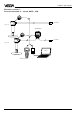
Setup Adjustment with PC and adjustment program VVO (electronics version B, I, K and L) With the adjustment program VVO (VEGA Visual Operating) on the PC, you can conveniently adjust the pressure transmitters with electronics version B, I, K and L. The PC communicates with the sensor through the interface converter VEGACONNECT 2 or the standard RS 232 interface cable. A digital adjustment signal is superimposed on the signal and supply cable.
Setup S Z ti Op 1 2 3 4 5 + - 4...20mA 12V...36V DC Bedieneinsatz operating unit Note: - A modification of zero does not influence the span, i.e. the measuring range final value is simply shifted. - It is also possible to adjust currents for partial fillings or partial pressures, e.g. 8 mA for 25 % and 16 mA for 75 %.The pressure transmitter then automatically calculates the values for 0 % or 100 % (only possible with a level difference >3.3 %).
Setup 4.4 Setup with HART ® handheld Sensors with electronics versions I, K and L can be set up with the HART ® handheld. A special DD (Data Device Description) is not necessary. Just connect the HART® handheld to the sensor signal cable after you have connected the sensor to supply voltage. Note: If the resistance of the voltage supply is less than 250 Ω, a resistor must be looped into the signal/connection cable during adjustment.
Setup The most important adjustment steps On the following four pages you see a menu schematic of the HART® handheld in conjunction with pressure transmitters D80 … D87. The most important adjustment steps are marked in the menu schematic with the letters A … D. If you are not familiar with HART® handheld, please note: After entering a parameter, first push the " ENTER" key. The adjustment is saved in the handheld, but not in the sensor itself. Generic: SENSOR PV LVR 0.000 mbar 10.000 mbar 4.1 (5.
Setup HART ® menu schematic Switch on: Hart Communicator Self Test in Progress Firmware Rev: F2.2 Module Rev: 3.6 01992-96 FRSI after approx. 20 s Generic: D84 Online(Generic) 1 Device setup 2 PV 80.007 mbar 3 PV AO 17.594 mA 4 PV LRV 0.000 mbar 5 URV 100.000mbar HELP SAVE Set up the sensor in the sequence of the letters A, B, C and D (adjustment without medium). For the adjustment with medium you set up the sensor in the sequence A1, B1, C and D. Generic: D84 Process variables 1 Snsr 84.
Setup 1.1.1 Generic: D84 PV 83.454 mbar Safety enquiry acknowledgement HELP EXIT 1.1.2 Generic: D84 PV % rnge 83.385 % 1.2.2 Generic: D84 Choose analog output level 1 4 mA 2 20 mA 3 Other 4 End ABORT ENTER Input of individual current values for test purposes (simulation of measured value) A1 } B1 1.2.3 Generic: D84 Calibration 1 Apply values 2 Enter values Empty and full adjustment with medium (see next page) HELP SAVE HOME HELP EXIT 1.1.3 Generic: D84 AO1 17.327 mA HELP SAVE C EXIT 1.
Setup HART ® menu schematic (continuation) 1.2.3.1 1.2.3 Generic: D84 Calibration 1 Apply values 2 Enter values 1.2.3.1 Safety enquiry acknowledgement Generic: D84 Set the: 1 4 mA 2 20 mA 3 Exit ABORT OK ABORTENTER HELP SAVE HOME Generic: D84 Enter values 1 PV LRV 0.000 mbar 2 URV 100.000 mbar 3 PV USL 4 PV LSL 0.000 mbar HELP A1 Empty adjustment with medium Generic: D84 Apply new 4 mA input HOME 1.2.3.2 like display 4.1 like display 4.
Setup 1.2.3.1.1 Generic: D84 Current applied process value: 97.112 mbar 1 Set as 4 mA value 2 Read new value 3 Leave as found ABORTENTER Generic: D84 Current applied prosess value :96.262 mbar 1 Set as 20 mA value 2 Read new value 3 Leave as found ABORT ENTER 1.2.3.1.2 1.2.3.1.1.1 Generic: D84 Set the: 1 4 mA 2 20 mA 3 EXIT Generic: D84 Apply new 4 mA input ABORT OK Generic: D84 Current applied process value: 96.
Setup 5.5 Adjustment with PC directly on the sensor (electronics versions I, K and L) For connection of the PC to the sensor, the interface converter VEGACONNECT 2 is required. Connection of the PC to the sensor Insert VEGACONNECT into the serial interface of the PC and insert the two-wire cable of VEGACONNECT into the CONNECT socket of the sensor. Connection of the PC to the signal cable Connect the two-wire cable of VEGACONNECT 2 to the signal cable leading to the sensor.
Setup If you have already connected the PC with the adjustment software VVO to your measuring system, • first switch on the power supply of the connected sensor • switch on the PC and start the adjustment software VVO. • Choose with the arrow keys or the mouse the item "Planning" on the entrance screen and click to "OK ". The adjustment program (VVO), called in the following VVO, gets into contact with the connected sensor… …and indicates after a few seconds if and with which sensor a connection exists.
Setup Note: If you connect the adjustment software (VVO) to a sensor from which data has already been saved, you are asked if the saved data should be transferred to the sensor or if you want to transfer the sensor data to the database of VVO (the available data of the current sensor will be overwritten). If you don’t get communication with the sensor, check the following: - Is the sensor being supplied with sufficient voltage (min.
Setup • Choose in the menu window "Instrument data parameter adjustment" the menu item "Adjustment". • In the menu window "Adjustment " you click to "Min/Max-adjustment " (zero/span). Parameter adjustment/Adjustment In the menu " Instrument data/Parameter adjustment" you carry out all important sensor adjustments. • Choose the menu "Instrument data/Parameter adjustment". You can carry out the min./max. adjustment with or without medium. Generally you will carry out the adjustment without medium.
Setup • Click to "Offset correction". • When the sensor is unpressurised and in installation position, confirm the safety enquiry with "OK". The example shows an absolute pressure transmitter with a measuring range of 0 … 1000 mbar, with which low pressures (partial vacuum) are measured. The min. value was set to 50 mbar and the max. value (span) to 1000 mbar (i.e. the final value of the measuring range). You see the actual measured value from the sensor. • Click to "Correct".
Setup Again choose the menu "Offset correction" and you see the corrected zero value. Note: The menu item "Real value correction " enables the correction of the actual pressure by means of a reference value. This corrects the measuring characteristics in a way similar to the offset correction. Conditioning/Linearisation In the menu " Instrument data/Parameter adjustment/Conditioning/Linearisation " you allocated a filling quantity (volume) to the level (filling height).
Setup In the field "Transfer measured value" the current pressure as a percentage of the adjusted span is displayed. The measuring span has already been adjusted with the min./max adjustment. In our example this is in the range between 50 … 1000 mbar.
Setup Meas. data information • Click to " Meas. data info". Saved sensor data can be transferred later on to other sensors. For example, if you have a system with several of the same storage vessels and identical sensors, it is sufficient to configure one sensor and then transfer the settings to the other sensors. All available sensor information is displayed. With the button "reset " you can delete the pressure and temperature history saved in the sensor.
Diagnostics 6 Diagnostics Maintenance The pressure transmitter D81 is maintenance free. Should dismounting of the pressure transmitter (e.g. for vessel cleaning) be necessary, we recommend the use of new seals. Use only original seals from VEGA. Checking electrical connections Pressure transmitter terminals 1 2 3 Voltage V Current mA External energy source + ~ mA Current Remedying faults Through continuous self-monitoring, series 80 pressure transmitters offer maximum reliability.
Instrument modification 7 Instrument modification 7.1 Retrofitting the adjustment insert Such a retrofitting can be necessary, e.g. when a pressure transmitter with factory settings must be adapted to changed measurement conditions. Note the following retrofit procedure: • remove the outdated terminal insert • mount new adjustment insert • set up pressure transmitter acc. to chapter "5 Setup" Remove the outdated terminal insert 1 2 3 4 5 6 Separate pressure transmitter from power supply.
Notes 42 Pressure transmitter D81
Notes Pressure transmitter D81 43
VEGA Grieshaber KG Am Hohenstein 113 D-77761 Schiltach Germany Phone +49 (0) 7836 50-0 Fax +49 (0) 7836 50-201 E-Mail info@de.vega.com www.vega.com ISO 9001 All statements concerning scope of delivery, application, practical use and operating conditions of the sensors and processing systems correspond to the latest information at the time of printing. Technical data subject to alterations 2.