
Manual


4 Connecting
4.1 Connect
ion procedure
The electrical connection is carried out according to the operating
instructions manual of the respective sensor.
4.2 Wiring plan
2
4
3
1
3
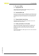
Fig. 3: Wire assignment, connection cable
1 Brown (+) and
blue (-) to the sensor
2 brown (+) and blue (-) to power supply or to the processing system
3 Shielding
4 Breather capillaries
Wire colour Terminal, electronics module
Brown 1
Blue 2
Black
2
3
1
3
Fig. 4: Wire assignment, connection cable
1 Brown (+) and
blue (-) to the sensor
2 brown (+) and blue (-) to power supply or to the processing system
3 Shielding
Wire colour Terminal, electronics module
Brown 1
Blue 2
VEGABAR series 50 and
60
VEGAPULS, VEG
ASO
N,
VEGA
CAL serie
s 60,
VEGAFLEX series 60
and 80,
Connection cable IP 66/IP 68 (1 bar) • Retrofit
set/Accessory for plics sensors 7
4 Connecting
34107-EN-120524