
Manual


6
6
5
5
655
6
2
3 4
1
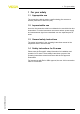
Fig. 2: Position of the
cable gland and filter element with the different housing
versions
1 Stainless steel (electro-polished)
2 Stainless steel (precision casting)
3 Alu double chamber
4 Alu single chamber
5 Cable gland
6 Filter element
Proceed as follows for mounting:
1 Unscrew the existing cable gland
2 Screw in the cable gland of the IP 66/IP 68, 1 bar connection cable
3 Connect the wires according to chapter "Connect"
4 Unscrew the filter element (consisting of four parts)
5 Screw in the blind stopper
6 Lead the loose end of the connection cable into a suitable
connection box with pressure compensation, e.g. VEGABOX 02
6 Connection cable IP 66/IP 68 (1 bar) • Retrofit
set/Accessory for plics sensors
3 Mounting
34107-EN-120524