
Manual


3 Mounting
3.1 Mounting
preparations
The following tools are required for mounting:
l Spanner SW 24 for unscrewing the cable gland
l Spanner SW 9 for unscrewing the filter element
l Screwdriver size 4 for screwing in t he blind stopper
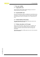
The blind stopper consists of adapter, O-ring and closing screw. It is
assembled according to the following drawing:
1
2
3
Fig. 1: Assembly of blind
stopper
1 Adapter
2 O-ring
3 Closing screw
3.2 Mounting steps
The illustration below shows the position of the cable gland and the
filter element in the respective housing:
Tools
Blind stopper
Connection cable IP 66/IP 68 (1 bar) • Retrofit
set/Accessory for plics sensors 5
3 Mounting
34107-EN-120524