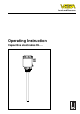
Level and Pressure Operating Instruction Capacitive electrodes EL …
Safety information Safety information The described module must only be installed and operated as described in this operating instruction. Please note that other action can cause damage for which VEGA does not take responsibility.
Contents Contents Safety information ......................................................................... 2 1 Product description 1.1 Function and configuration ................................................... 4 1.2 Types and versions ............................................................... 6 1.3 Technical data ....................................................................... 8 1.4 Approvals ............................................................................ 15 1.
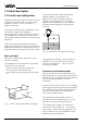
Product description 1 Product description 1.1 Function and configuration Capacitive electrodes series EL detect levels of virtually all kind of products, whether liquids, granules or pastes. This is also valid for adhesive products. The electrode and the vessel wall are the capacitor plates. The medium is the dielectricum. Due to the higher dielectric constant value (DK-figure) of the medium against air, the capacitance of the capacitor increases with the degree of the electrode covering.
Product description In addition to the continuous measurement also level detection is possible (VEGAMET or VEGAMET + VEGASEL). Level detection Level switches should signal when certain levels are reached, e.g. max. or min. levels. These levels are detected at a fixed point and converted into a switching command. For level detection capacitive electrodes EL with the appropriate signal conditioning instruments VEGATOR are available.
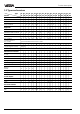
Product description 1.
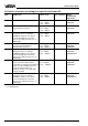
Product description Type Version EL EL EL EL EL EL EL EL EL EL EL EL EL EL EL EL EL EL EL 11 18 21 24 26 28 29 31 33 34 42 52 53 601) 611) 82 92 84 86 Isolation material PTFE • PP • • • • • • • • • • • • PE/PA 12 • PFA • FEP • • • PE • • • • Ceramic • • Concentric tube Steel • • • StSt • • • Screening tube (option) Steel • • • • • • • • • StSt • • • • • • • • • Steel • • • • • • •2) •2) StSt • • • • • • •2) •2) PA • • • • • T
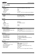
Product description 1.3 Technical data Housing Housing material Protection - plastic housing - StSt-housing Cable entry Terminals plastic PBT (Polyester) or StSt (1.4301) IP 66 IP 67 1 x Pg 16 for max. 1,5 mm2 cross-section area of conductor Mechanical connection Material Thread Flange galvanized steel (St 37), 1.4571 (StSt), Aluminium G 11/2 A or 11/2" NPT different flange versions Electrode Material Length - rod - cable Isolation Max. tensile load - EL 31 - EL 33, 34, 52 53 steel (St 37), 1.
Product description Weight Basic weight (e.g. EL 24) Rod weight approx. 1,4 kg approx. 1,4 kg/m Approvals (deviating technical data) Supply and signal circuit in classification intrinsic safety EEx ia IIC only for connection to a certified intrinsically safe circuit with the following max.
Product description Oscillators in two-wire technology for capacitive electrodes EL Type Application Meas.
Product description Level Meas. value Oscillator E18 Oscillator E18 with patented processing (phase selective admittance processing) extends the application area of the capacitive level measurement technology. In conjunction with the fully insulated rod electrode EL 24 the oscillator E18 compensates also strong conductive build-up. Mounted into an individual rod or cable electrode type EL, E18 ensures also the exact measurement of solids with varying humidity contents. fully insulated electrode 15 % vol.
Product description Product temperature and operating pressure 1 bar The figures of the tables relate each to the figures on this page. The stated pressures are valid for screw connections G 11/2 A, NPT 11/2“ and R 11/2. Boltings DN 50 acc. to DIN 11 851 only up to max. 25 bar. With flange version you have to note their nominal pressure. All electrodes are also suitable for vacuum (-1 bar).
Product description Electrode type PE PP PTFE PE/PA 12 PFA Mechanical connection, Aluminium EL 11 - 7 8 - - EL 21 7 - 8 - 8 EL 26 - - 8 - 8 EL 31 - 7 8 - - EL 33 - - 8 - - bar EL 34 unpressurized - - - 7 - 16 EL 42 - - 8 - - EL 52 - - 8 - - Isolation 7 bar EL 53 - - - 7 - EL 82 unpressurized - - 9 - - EL 92 - - 9 - - 16 0 –30 60 80 °C EL 86: unpressurized EL 34: unpressurized 8 0 –30 100 °C EL 82: unpressurized EL 92: up
Product description Electronics temperature The following product and ambient temperatures must be kept so that the limit temperature on the electronics will not be exceeded. The stated values are definite for applications in hazardous areas. Note for these applications also the legal documents (test certificates, type approvals and conformity certificates).
Product description 1.4 Approvals CE-approval - The capacitive electrodes type EL are available with the following approvals: explosion protection (CENELEC, Zone 0) overfill protection acc. to WHG, (VbF) dust-explosion protection Zone 10 ship approvals (GL, LRS, ABS) The capacitive electrodes type EL meet the protective regulations of EMVG (89/336/EWG) and NSR (72/23/EWG). The conformity has been judged acc.
Product description Level detection with fault monitoring Instrument Conformity certificate PTB-no. Oscillator Conformity certificate PTB-no. Level switch VEGATOR Conformity certificate PTB-no. Capacitive electrodes 1) Ex-96.D.2021 E15 Ex Ex-95.D.2040 U 521 Ex, 522 Ex 523 Ex, 527 Ex 621 Ex, 622 Ex Ex-95.D.2065 X Ex-95.D.2073 X Ex-96.D.2068 Capacitive electrodes 2) Ex-96.D.2021 E18 Ex Ex-95.D.4042 U 521 Ex, 522 Ex 523 Ex, 527 Ex 621 Ex, 622 Ex Ex-95.D.2065 X Ex-95.D.2073 X Ex-96.D.
Product description Level detection with fault monitoring Instrument Conformity certificate PTB-no. Oscillator Conformity certificate PTB-no. Level switch VEGATOR Conformity certificate PTB-no. Capacitive electrodes 1) Ex-95.D.2097 E15 Ex Ex-95.D.2040 U 521 Ex, 522 Ex 523 Ex, 527 Ex 621 Ex, 622 Ex Ex-95.D.2065 X Ex-95.D.2073 X Ex-96.D.2068 Capacitive electrodes 2) Ex-95.D.2097 E18 Ex Ex-95.D.4042 U 521 Ex, 522 Ex 523 Ex, 527 Ex 621 Ex, 622 Ex Ex-95.D.2065 X Ex-95.D.2073 X Ex-96.D.
Product description StEx Zone 10 Continuous level measurement with auxiliary level switch Instrument Oscillator Level switch Aux. level switch VEGASEL Certificate BVS-no. Capacitive electrodes 1) E17 EX E18 EX VEGAMET 602 EX 513 EX, 514 EX 515 EX VEGATRENN 544 Ex All aux. level switches with 0/4…20 mA or 0/2 … 10 V input 96.Y.8006 1) EL 11 EXS, EL 31 EXS, EL 60 EXS, EL 61 EXS, EL 82 EXS Level detection Instrument Oscillator Level switch VEGATOR Certificate BVS-no.
Product description 1.5 Dimensions Dimensions of the capacitive electrodes type EL Type EL 11 (partly insulated) ~28 126 SW 30 G 11/2 A 50 G 1/2 A ø10 12 20 SW 60 L (max. 4000 mm) Pg 16 35 Type EL 18 with separate housing ø32 75 57 ø90 Type EL 18 (partly insulated) Fixing plate ø6 L ø6,6 80 L1 ø20 80 ø15 Isolation length L1: PP: 100 mm PTFE: 50 mm StEx: max. 100 mm L (min. 100 mm, max.
Product description Type EL 28 (fully insulated) Type EL 28 with separate housing Type EL 29 (fully insulated) ø90 SW 30 G 1/2 A ~28 174 75 L (max. 4000 mm) 57 ø32 Pg 16 12 ø10 L ø6,6 80 25 Fixing plate 80 ø14 48 L (min. 120, max.
Product description ø90 Type EL 52 (fully insulated) ø90 ~28 Pg 16 ~28 ø90 126 126 ~28 Type EL 53 (fully insulated) Pg 16 126 Type EL 42 (fully insulated) Pg 16 35 20 SW 60 20 35 SW 60 20 35 SW 60 G 11/2 A G 11/2 A G 11/2 A ø15,5 ø11 ø8 ø6 ø5 ø3 200 ø40 ø20 36 ø40 120 125 200 120 200 L L L ø3 ø40 ø20 36 ø40 L (min. 400 mm, max. 25000 mm) L (min. 400 mm, max. 25000 mm) Type EL 82 / EL 92 (partly / fully insulated) (plate electrode) L (min. 400 mm, max.
Product description Type EL 60 (partly insulated, high temperature electrode) ø90 ~28 Type EL 86 (annular electrode) ~28 ø90 ~28 106 126 126 ø90 Type EL 61 (partly insulated, high temperature electrode) Pg 16 SW 60 Pg 16 SW 60 180 180 23 23 200 200 65 Pg 16 SW 60 G 11/2 A G 11/2 A ø38 L1 L1 ø38 i k Different versions: I: min. 100 mm … max. 400 mm k: min. 160 mm … max. 450 mm D: min. 190 mm … max. 480 mm 100 L L D 200 ø8 ø15 ø40 L (min. 400 mm, max.
Product description Housing ~28 ø90 22 ø88 ø88 22 Pg 16 106 126 120 Pg 16 Pg 16 ø85,5 ø85,5 Housing (V) of 1.4301, IP 67 for integral overvoltage protection Housing (A) of Aluminium, IP 54 with separate plastic housing, IP 66 and triax cable connection. In Ex-applications the connection cable can have a length of Pg 16 max. 8 m. 44 145 Pg 13,5 Pg 13,5 76 70 Screw adapter of PP or PTFE ø90 ~28 Housing (V) of 1.
Product description 1.6 Type plate Configuration of the type plate (example) Please check before mounting and electrical connection if you use the suitable instrument. Please note the type plate which is located as follows: 1 VEGA® EL 21 EX0 2 3 type EL21EX0.XGBASTX see PTB no. EX-96.D.2021 EEX ia IIC T6 techn. data see document. / certificates protection: IP 66; 01/PTB-no. Ex-96.D.2021 ser. no. 10612892 length………mm AB-NR.
Mounting 2 Mounting 2.1 Mounting instructions General The different mediums and the requirements to the measurement require different installation positions. Hence note the following instructions. Length of the level electrode Note when ordering the electrodes, that the electrode must be sufficiently covered at the requested level according to the electrical features of the medium (DK-value). E.g.
Mounting Shortening of the electrode Carry out an adjustment. The instruction is under "4.1 Adjustment“. Fully insulated electrodes are fixed dimensioned and their dimensions must not be modified. Any modification will destroy the instrument. Partly insulated cable or rod electrodes can be shortened afterwards. Note that due the own capacitance change also the switch point can change. When the cable is extremely shortened, it can happen that the electrode cannot be adjusted.
Mounting Humidity from outside Aluminium vessel Turn the cable entries of horizontally mounted instruments after installation to the bottom to avoid humidity ingress. The instrument housing can be hence rotated by approx. 330°. For vertically installed electrodes loop the connection line to the electrode housing to the bottom so that rain and condensation water can drain off. In Aluminium vessels use an electrode with steel mounting thread.
Mounting Continuous electrodes max. 80 mm With electrodes, delivering continuous measured values, the electrode must only be installed vertically. Should the installation from top not be possible, the electrodes can also be mounted laterally. When in the installation place of the electrode there are struts or a roof, you should check if a rod electrode with the required length can be mounted. If mounting of a rod electrode is not possible, use a cable electrode. Fig. 2.
Mounting Material cone Note when installing the electrodes into the vessel, that material cones can be caused with solids which can change the switch point. We recommend to choose an installation place where the electrode detects an average value of the material cone. According to the position of the filling and emptying opening in the vessel, the electrode must be installed appropriately. To compensate meas. errors caused by the material cone, you should install the electrode at a distance of approx.
Electrical connection 3 Electrical connection 1 3.1 Connection instructions Note Switch off the power supply before starting connection work. 2 14 The electrical connection must be carried out dependent on the integral oscillator. The integral oscillator is stated on the type plate on the oscillator. Connect the supply voltage acc. to the following connection diagrams. 13 3 4 Note If strong electromagnetic interferences have to be expected, we recommend to use screened cable.
Electrical connection 3.2 Connection plan The electrical connection of the sensor on the signal conditioning instrument is stated in the operating instruction of the appropriate signal conditioning instrument. Note The oscillator is independent of the electrode and can be exchanged locally. As the oscillators have certain tolerances (approx. 5 %), it can be necessary to re-adjust the signal conditioning instrument after having exchanged the electronics.
Electrical connection Capacitive electrode with external overvoltage protection unit Vessel without cathodic corrosion protection Ex-area Not-Ex-area (control room) either overvoltage arrester B62 - 36 G Ex 0 (metal housing) or B62 - 36 G Ex (plastic housing) (Li = 0,15 mH, Ci = 1,5 nF) Electrode EL Outer isolation Outer isolation B 1 2 either overvoltage arrester A1 Typ A2 B62-36G Signal conditioning instrument or safety barrier A E1 A1 Typ E2 B62-36G A2 E1 E2 Screen Screen min.
Electrical connection Vessel with cathodic corrosion protection Ex-area Not-Ex-area (control room) either overvoltage protection instrument B62 - 36 G Ex 0 (metal housing) or B62 - 36 G Ex (plastic housing) Metal housing (Li = 0,15 mH, Ci = 1,5 nF) without earthing Electrode EL Outer isolation B 1 2 Outer isolation A1 Typ A2 B62-36G either overvoltage protection instrument Signal conditioning instrument or safety barrier A Typ E1 A1 E2 B62-36G A2 E1 E2 Screen Screen min.
Electrical connection Separate housing When there are ambient temperatures of more than 80° C on the housing, a temperature adapter must be used or the electronics must be separated from the electrode and located at a cool place. Hence the electronics can be mounted in a separate housing at a distance of up to 8 m from the electrode. Electrode and housing are dispatched completely mounted. Carry out the adjustment according to the following figures. Only use VEGA-triax cable.
Set-up 4 Set-up 4.1 General adjustment When you state with the order already the measured product, the electrode will be adjusted appropriately. The dielectric constant value and the conductivity of the product as well as the electrode length are considered. The figures in brackets relate to the figure under chapter “3 Electrical connection“. During set-up the electrode must be adjusted with the original medium. For adjustment of the electrode you have to open the housing cover.
Set-up 4.2 Level detection Vertically installed electrodes • Set the changeover switch on the oscillator of the electrode to step I. • Choose on the signal conditioning instrument the desired mode (A - overfill protection, B protection against dry running of pumps). • Fill the vessel up to the requested level. • Carry out the adjustment. Turn the potentiometer of the signal conditioning instrument (VEGATOR) very slowly until the control lamp changes condition. Should the adjusted meas.
Set-up 4.3 Continuous level measurement When you have already stated the measured product with the order, the oscillator of the electrode is already preadjusted. In this case the measured product is mentioned on the order confirmation. • Choose with the changeover switch on the oscillator of the electrode the step according to the following table. Note the column corresponding to your medium and choose by means of the length of your electrode the suitable range.
Set-up Signal conditioning instrument VEGAMET series 300 In case the electrode is not already preadjusted, you have to choose the meas. range. • Adjust the changeover switch on the capacitive electrode EL according to the table on the previous page. • Turn the potentiometer for full adjustment approx. 22 turns clockwise. • Empty the vessel to the desired min. level. • Turn the potentiometer for empty adjustment anticlockwise until the pointer of the indicating instrument is set to 0.
Diagnosis 5 Diagnosis 5.1 Simulation Test switch For simulation of a switching condition, a test switch can be optionally integrated in the housing. By pushing the test switch an additional capacitance is switched. Hence only the function of the oscillator and the connected instruments are tested. Note When the changeover switch is set to position 3, it can be possible that the connected capacitance is not sufficient to carry out a test. The test switch can be only used for simulation of a max.
Diagnosis 5.4 Failure removal Failure Measure, failure removal The red failure LED of the signal conditioning instrument lights Check the sensor inputs on the following failures: - Sensor not connected correctly - Sensor line interrupted - Supply voltage too low Check if the sensor is connected correctly. - Failures on the sensor, effecting a current change below 2 mA or above 23 mA lead to a fault signal on the signal conditioning instrument. Measure the current on the connection line to the sensor.
Diagnosis b. Current value > 22 mA - Check all connections and the connection line to the sensor. - When the red failure lamp still lights, separate the sensor from the connection line and connect a resistor of 1 kΩ . When the signal lamp extinguishes, the sensor is defect. Check the connected sensor. - When the failure lamp continues to light, connect the sensor again. Separate the signal conditioning instrument from the connection line and connect a resistor of 1 kΩ to the sensor input.
Diagnosis Contact 4 against middle pin (1) The resistance must be 1 MΩ . If the resistance is less, this means humidity in the housing or a failure in the electrode isolation. A possible reason could be a not isolated electrode which is used in conductive (humid) product. If the resistance is higher or if the connection is interrupted, the reason is mainly a bonding failure in the adapter plate or a defect resistor due to strong electrostatic discharge. In both cases the electrode must be repaired at VEGA.
Notizen Capacitive electrodes EL … 43
VEGA Grieshaber KG Am Hohenstein 113 D-77761 Schiltach Phone (0 78 36) 50 - 0 Fax (0 78 36) 50 - 201 e-mail vega@vega-g.de ISO 9001 Technical data subject to alterations 2.