Level and Pressure Operating Instructions Capacitive electrodes EL 4 … 20 mA - Compact
Safety information Please read this manual carefully, and also take note of country-specific installation standards (e.g. the VDE regulations in Germany) as well as all prevailing safety regulations and accident prevention rules. For safety and warranty reasons, any internal work on the instruments, apart from that involved in normal installation and electrical connection, must be carried out only by qualified VEGA personnel.
Contents Contents Safety information ......................................................................... 2 Note Ex area ................................................................................. 2 1 Product description 1.1 Function and configuration ................................................... 4 1.2 Types and versions .............................................................. 5 1.3 Technical data ....................................................................... 7 1.
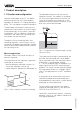
Product description 1 Product description 1.1 Function and configuration Capacitive electrodes series EL can detect the level of practically any kind of product, regardless of whether it is a liquid, powder or paste. This also applies to adhesive products. The electrode and the vessel wall are the capacitor surfaces. The medium is the dielectric.
Product description 1.
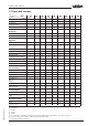
Product description Type EL 11*) EL 21*) PTFE • • PP • Version EL 24*) EL 29 EL 31*) EL 33 EL 42*) EL 52 • • • • EL 53 Insulation material5) • PE/PA 12 • PFA • FEP • PE • • Screening tube Steel • • Stainless steel (1.4435) • • Screening tube (option) Steel • • • • • • • Stainless steel • • • • • • • Temperature adapter (option) Steel • • • • Stainless steel (1.
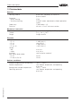
Product description 1.3 Technical data Housing Housing material Protection - plastic housing - Aluminium housing Cable entry Terminals plastic PBT (Polyester) or Aluminium plastic-coated IP 66 IP 66/67 (meets requirements of both protection types) 1 piece M20 x 1.5 for max. 1.5 mm2 wire cross-section Mechanical connection Material Thread Flange galvanized steel (St 37), 1.
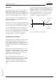
Product description Oscillators CAP E32 Ex, CAP E32 H Ex Protection class Overvoltage category Frequency Capacitance ranges Supply voltage Permissible residual ripple Potential separation II III 300 KHz 0 … 3000 pF 12 … 36 V DC in Ex applications note the permissible electrical connection values stated in the certificate USS less or equal 1 V min. 500 V DC Load in Ohm 1000 800 600 200 12 18 24 30 36 Supply voltage in V Accessory Fixing spring of 1.4571 - length - tensile force approx.
Product description Oscillator The oscillator CAP E32 (H) Ex with patented processing (phase-selective admittance processing) extends the area of application of capacitive level measurement technology. This function can be switched on, see 4 Setup. If the moisture content goes above 15 % vol., the fully and partly insulated electrodes react differently (see also „Fig. 1.3 Varying moisture content“).
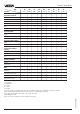
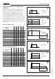
Product description Product temperature1) and operating pressure1) 40 0 -30 PE PP PTFE PE/PA12 PFA FEP EL 11 - 1 3 - - - 60 80 ˚C bar 63 40 16 100 ˚C 0 -50 Electrode type EL 53: PE and PE / PA 12: up to 16 bar EL 34: unpressurised 16 Process fitting, 1.4571 Insulation 1 bar The numbers in the tables all relate to the graphs on this page. The stated pressures are valid for screw connections G 1½ A, 1½ NPT and R 1½. Boltings DN 50 acc. to DIN 11 851 only up to max. 25 bar.
Product description Process fitting, Aluminium PTFE PE/PA 12 PFA 7 8 - - 8 - 8 8 - - 8 - - - 8 - - bar - - 8 - - 16 - - - 7 - Electrode type PE PP Insulation EL 11 - 7 EL 21 7 - EL 31 - 7 EL 33 - - EL 42 - EL 52 EL 53 bar 16 0 -30 60 80 ˚C 8 -50 0 100 ˚C Process fitting, plastic (screw adapter) 9 bar Electrode type PVC PP PTFE Insulation EL 29 9 9 9 22652-EN-020809 1) 2) 40 -20 PVC, PP: unpressurised up to 80°C PTFE: 3 bar, -20 … 10
Product description Electronics temperature Product and ambient temperatures must be kept at levels that do not exceed the limit temperature of the electronics.
Product description 1.4 Approvals Explosion protection Only certified capacitive electrodes EL** Ex 0 may be used in hazardous areas with combustible gases, vapours or fog. Capacitive electrodes EL** Ex 0 are suitable for use in hazardous areas of zone 1 and zone 0. The explosion protection provided by these instruments is certified by the EC type approval and the conformity certificate, possibly with national zone 0 annex, issued by the approval authority.
Product description 1.5 Dimensions Dimensions of capacitive electrode type EL … Ex 0 Type EL 11 (partly insulated) (Ex 0) 85 Type EL 21 (fully insulated) (Ex 0) 85 32,5 L (min. 120/max. 4000 mm) L (min. 100/max. 4000 mm) Insulation length L1: PP: 100 mm PTFE: 50 mm StEx: max. 100 mm A L (min. 100 mm, max. 4000 mm) L (min. 100 mm, max. 4000 mm) Type EL 31 (partly insulated) 85 32,5 (Ex 0) Type EL 29 (fully insulated) 32,5 158 Ø 12 Ø 14 L (min. 120 mm, max.
Product description Type EL 52 (fully insulated) 85 32,5 32,5 85 32,5 90 M20x1,5 M20x1,5 90 SW 60 20 35 SW 60 20 35 Housing 90 85 Type EL 53 (fully insulated) G 1½A G 1½A M20x1,5 ø11 ø15,5 ø6 ø8 Screw adapter of PP or PTFE ø40 ø40 ø20 36 ø40 ø20 36 ø40 L (min. 400 mm, max. 25000 mm) 20 44 125 120 200 200 L L Housing of plastic/ Aluminium G 1½ A L (min. 400 mm, max.
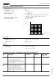
Product description Contents of the type plate (example) 1.6 Type plate Before mounting and electrical connection, please make sure you are using a suitable instrument. Note the type plate which is located as shown below: VEGA® EL 11 1 2 3 Type plate 4 type EL11EXO.XGBVSTXXVKXX 9 see PTB Nr. EX-98.E.2085 EEx ia IIC T6 0032 II 1/2G EEx ia IIC T6 PTB 98 ATEX 2086 techn. data see document. / certificates 1998 8 protection: IP 66/67 Insp. ser. no. 10612892 length: 400mm VVO: 02 Ord. no.
Mounting 2 Mounting 2.1 Mounting instructions General Different mediums and measurement requirements make different installation positions necessary. Please note the following points. Lateral load Make sure that the electrode is not subjected to strong lateral forces. Mount the electrode in a position in the vessel where no disturbing factors, e.g. stirrers, filling openings etc. are present. This is especially important for very long rod and cable electrodes. Downward forces Strong downward forces, e.g.
Mounting Shortening the electrode Filling opening Fully insulated electrodes have fixed dimensions which must not be modified in any way. Any modification will destroy the instrument. Install the electrode such that it does not protrude directly into a strong filling stream. Should such an installation location be necessary, mount a suitable protective sheet in front of the electrode, e.g. L 80 x 8 DIN 1028, etc. Partly insulated cable or rod electrodes can be shortened if necessary.
Mounting Metal vessel Cable electrodes in solids Make sure that the mechanical connection of the electrode to the vessel is electrically conductive in order to ensure sufficient grounding. Depending on the type of solid, the filling method and its location, the cable electrode may “float“ in spite of the gravity weight. The electrode (cable) is pushed by the solid against the vessel wall or to the surface, thus causing incorrect measured values. This should be avoided during continuous measurement.
Mounting Lateral mounting With measuring probes that deliver continuous measured values, the electrode must be installed vertically. If installation from the top is not possible, the electrodes can also be mounted laterally (fig. 2.5). Under accessories in our price list, you can find a screening tube and a closing cone or an angled rod electrode with which the instrument can also be laterally mounted.
Mounting Material cone When installing the measuring probe in a vessel, be aware that conical heaps which alter the switching point can form in solid material. We recommend choosing an installation location that enables the electrode to detect the average value of the conical heap.
Electrical connection 3 Electrical connection 3.2 Wiring plan 3.1 Connection instructions Note The oscillator is independent of the electrode and can be exchanged on site. Note Switch off the power supply before starting connection work. Connect the supply voltage according to the following connection diagrams. + 4 … 20 mA – A multimeter can be connected to terminals 3 and 4 for setup. This connection is not suitable for an indicating instrument.
Electrical connection Qualified personnel Instruments which are operated in Ex areas must only be connected by qualified personnel. They have to note the installation regulations and the attached type approval certificates and conformity certificates. If the capacitive electrodes are to be mounted on vessels which must be protected against the danger of ignition by lightning (acc. to TRbF 100 no. 8, para.
Overvoltage protection unit mounted to oscillator Oscillator Non (Ex) area (Ex) area Zone1 CB 2-36 2 1 Li, Ci of the oscillator with overvoltage protection unit Li = 0.27 mH Ci = 8.5 nF Screen External ground terminal CAP E32(H)EX Control room optionally: Overvoltage protection insert Type B62-36G Vessel Zone 0 E2 E1 Internal ground terminal Li=0.15 mH Ci=2.
22652-EN-020809 CB 2-36 2 1 CAP E32(H)EX Li, Ci of the oscillator with overvoltage protection unit Li = 0.27 mH Ci = 8.5 nF Oscillator External ground terminal Control room optionally: Overvoltage protection insert Screen Type B62-36G Internal ground terminal Vessel Zone 0 E2 E1 Li=0.15 mH Ci=2.
Setup 4 Setup 4.1 General adjustment The numbers in brackets relate to the illustration under “3 Electrical connection“. In the setup procedure, the electrode must be adjusted to the medium which will later be measured. In certain cases, a dry adjustment is also possible. The electrode can be adjusted in three different ways: • with the integrated oscillator • with the adjustment software VEGA Visual Operating (VVO from version 2.
Setup 4.2 Adjustment - Oscillators CAP E32 Ex and CAP E32 H Ex 2 1 0 8 1 2 3 4 1 Minus key 2 Rotary switch 3 Plus key 6 3 2 4 - + + - + 1 2 3 4 mA U = 12 … 36 V Rotary switch (2) With the rotary switch (10 steps) you select the appropriate mode. As soon as you continue turning the rotary switch, the modified value will be saved. 0 1 2 3 4 5 6 7 8 9 Operate Min. adjustment Max.
Setup We recommend that you connect an ammeter. See 3.2 Electrical connection. By doing this, you can monitor the current value during modification. If you hold the key pushed, the value changes automatically and with rising speed. The difference between min. and max. adjustment should be at least 20% or 3.2 mA. (+/-) (+) (-) set 20 mA increase current reduce current 3 Integration time If you want to set the integration time (damping), you have to set the rotary switch to position 3.
Setup Mode 2 = Phase angle 45° The capacitance and the ohmic conductance are measured separately, the capacitance value is corrected by calculating it with the ohmic conductance, so that measurement errors caused by conductive buildup or varying product moisture are compensated. Application: - highly conductive products - adhesive, conductive products - solids with fluctuating moisture content For applications in conductive, viscous liquids, you should use a suitable electrode of type EL 24.
Setup 4.3 Adjustment with VVO If oscillator CAP E 32 H Ex is installed, the electrode can also be adjusted via a PC with adjustment software VVO (from version 2.30). PC with VVO + - + 1 2 3 4 mA VVO recognises automatically the type of the connected sensor and immediately afterwards indicates with which sensor a connection exists. If you get no sensor connection, please check the following: - the supply voltage must be at least 12 V.
Setup 4.4 Adjustment with HART® handheld The capacitive electrodes EL with oscillator CAP E32 H Ex are HART® protocol capable and can be adjusted with a HART® handheld. HART® handheld + - + 1 2 3 4 mA 250 Ohm All relevant sensor functions can be executed with the HART® standard menus. A manufacturer-specific DDD (Data-Device-Description) is not necessary. Connect the HART® handheld to the sensor signal cable after you have connected the sensor to power supply.
Setup PLC with Ri < 250 Ohm + – 250 PLC Ri < 250 Fig. 1 PLC with Ri > 250 Ohm + PLC – Ri > 250 Fig. 2 VEGAMET signal conditioning instruments or VEGALOG VEGAMET VEGALOG + – Fig.
Setup Adjustment steps On the following pages you will see the menu schematic of the HART® handheld in conjunction with capacitive electrodes. The most important adjustment steps are marked in the menu schematic with the letters A … D. In a further safety enquiry you are asked to switch the system from manual to automatic operation. Confirm with „OK“. Generic: SENSOR - WARNINGReturn control loop to automatic control.
Setup HART® menu schematic Hart Communicator Self Test in Progress Firmware Rev: F2.2 Module Rev: 3.6 01992-96 FRSI after approx. 20 s Generic: Sensor Online(Generic) 1 Device setup 2 PV 3 PV AO 4 PV LRV 5 URV HELP SAVE Set-up the sensor in the sequence of the figures A, B, C and D (adjustment without medium). In case of adjustment with medium, set-up the sensor in the sequence A1, B1, C and D.
Setup 1.1.1 Generic: Sensor PV 0,2 m Confirm safety enquiry HELP EXIT 1.1.2 Generic: Sensor PV % rnge 8.945 % 1.2.2 Generic: Sensor Choose analog output level Individual current values for 1 4 mA test purposes (simulation of 2 20 mA measured values) 3 Other 4 End ABORT ENTER 1.2.3 Generic: Sensor Empty and full Calibration adjustment 1 Apply values with medium 2 Enter values (see next page) A1 } B1 HELP HELP EXIT 1.1.3 Generic: Sensor AO1 5.
Setup HART® menu schematic (continuation) Empty adjustment with medium 1.2.3.1 1.2.3 Generic: Sensor Calibration 1 Apply values 2 Enter values 1.2.3.1 Confirm safety enquiry Generic: Sensor Set the: 1 4 mA 2 20 mA 3 Exit A1 Generic: Sensor Apply new 4 mA input ABORT OK ABORTENTER HELP SAVE HOME 1.2.3.2 Generic: Sensor Enter values 1 PV LRV 2 URV 3 PV USL 4 PV LSL HELP B1 Generic: Sensor Apply new 20 mA input as display 4.1 as display 4.2 Indication of sensor meas. range limits } ABBR.
Setup 1.2.3.1.1.1 1.2.3.1.1 Generic: Sensor Generic: Sensor Current applied Set the: process value: 10.945 1 4 mA mbar 2 20 mA 1 Set as 4 mA value 3 EXIT 2 Read new value 3 Leave as found ABORT ENTER ABORT ENTER Generic: Sensor Current applied prosess value :85.281 mbar 1 Set as 20 mA value 2 Read new value 3 Leave as found ABORT ENTER 1.2.3.1.2 Generic: Sensor Set the: 1 4 mA 2 20 mA 3 Exit ABORT ENTER 1.2.3.1.2.1 1.4.3.1.
Diagnosis 5 Diagnosis 5.1 Simulation To simulate a certain filling level, you can call up the function “Simulation” in the oscillator, in the adjustment program VVO or in the HART® handheld. You hereby simulate a certain current. Remember that connected instruments, such as e.g. a PLC, react according to their settings and that alarms may be triggered or system functions activated. 5.2 Maintenance The instrument is maintenance-free. 5.
Diagnosis 5.4 Fault rectification Fault Rectifying measure Current value ≥ 22 mA Check the sensor inputs on the following failures: - short-circuit on the input - sensor not connected correctly - sensor cable interrupted - supply voltage too low or too high Measure the current on the connection cable to the sensor. Under normal conditions, the terminal voltage of the sensor is at least 12 V. 4 … 20 mA mA 1212 …… 2036 V V V 28 + 30 – 32 Sensor + + – – e.g.
Diagnosis Fault Rectifying measure Sensor defective, Measurement does react to level changes Test the internal connections: • Loosen the 4 screws of the housing cover with a Phillips screwdriver and remove the housing cover. • Loosen the two small screws with a Phillips screwdriver and pull the oscillator out of the housing.
Diagnosis Contact 4 and vessel The connection between contact 4 and the metal vessel (not instrument hexagon or electrode flange) should be as good as possible. Measure with an ohmmeter (range very low) the resistance value between contact 4 and the vessel. • Short-circuit (0 … 3 Ohm), optimum connection • Resistance > 3 Ohm - corrosion on the mounting thread or flange - possibly the mounting thread was covered with Teflon tape or a similar material Check the connection to the vessel.
22652-EN-020809 Notes 42 Capacitive electrodes EL 4 … 20 mA - Compact
Notes 22652-EN-020809 Capacitive electrodes EL 4 … 20 mA - Compact 43
VEGA Grieshaber KG Am Hohenstein 113 77761 Schiltach Germany Phone (07836) 50-0 Fax (07836) 50-201 E-Mail info@de.vega.com www.vega.com ISO 9001 All statements relating to scope of delivery, application, practical use and operating conditions of the sensors and processing systems correspond to the latest information at the time of printing. Technical data subject to alterations 2.