
Owner's manual
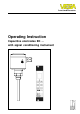
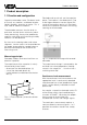
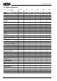
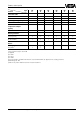
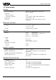
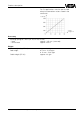
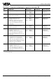
Table Of Contents
- Contents
- Safety information
- Note Ex-area
- 1 Product description
- 1.1 Function and configuration
- 1.3 Technical data
- 1.4 Approvals
- 1.5 Dimensions
- 1.6 Type plate
- 2 Mounting
- 2.1 Mounting instructions
- 3 Electrical connection
- 3.1 Connection instructions
- 3.2 Wiring plan
- 4 Set-up
- 4.1 General adjustment
- 4.2 Level detection
- 4.3 Continuous level measurement
- 5 Diagnosis
- 5.1 Simulation
- 5.2 Maintenance
- 5.3 Repair
- 5.4 Failure removal

8 Capacitive electrodes EK with signal conditioning instrument
Product description
1.3 Technical data
Housing
Housing material plastic PBT (Polyester) or Aluminium
plastic coated
Protection
- plastic housing IP 66
- Aluminium housing IP 66 and 67 (meets both protections)
Cable entry 1 pce. M20 x 1,5
Terminals for max. 1,5 mm
2
cross-section area of
conductor
Mechanical connection
Material 1.4435 (316 L)
Thread G
3
/
4
A or
3
/
4
“ NPT
G 1 A or 1“ NPT
Flange flange versions, plated
Electrode
Material EK 11 1.4435 (316 L)
EK 21 steel (St 37), 1.4435 (316 L)
EK 31 1.4401 (316 L)
EK 24, 42 1.4571 (316 L)
Length
- rod max. 3 m
- cable max. 20 m
Isolation see "Isolating materials"
Max. tensile strength
- EK 31 3 KN
- EK 42 3 KN
Ambient conditions
Ambient temperature on the housing -40°C … +80°C
Medium temperature see "Product temperature and operating
pressure"
Storage and transport temperature -40°C … +80°C
Operating pressure see "Product temperature and operating
pressure"
Oscillators E14, E15, E17, E18
Protection class II
Overvoltage category III
Meas. frequency see table on the following page
Capacitance ranges see table on the following page
Supply voltage 12 … 36 V DC (powered by signal conditioning
instrument)
Potential separation min. 500 V DC (except E14)