
Owner's manual
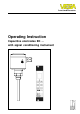
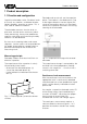
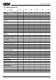
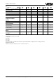
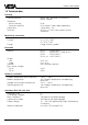
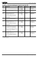
Table Of Contents
- Contents
- Safety information
- Note Ex-area
- 1 Product description
- 1.1 Function and configuration
- 1.3 Technical data
- 1.4 Approvals
- 1.5 Dimensions
- 1.6 Type plate
- 2 Mounting
- 2.1 Mounting instructions
- 3 Electrical connection
- 3.1 Connection instructions
- 3.2 Wiring plan
- 4 Set-up
- 4.1 General adjustment
- 4.2 Level detection
- 4.3 Continuous level measurement
- 5 Diagnosis
- 5.1 Simulation
- 5.2 Maintenance
- 5.3 Repair
- 5.4 Failure removal
6 Capacitive electrodes EK with signal conditioning instrument
Product description
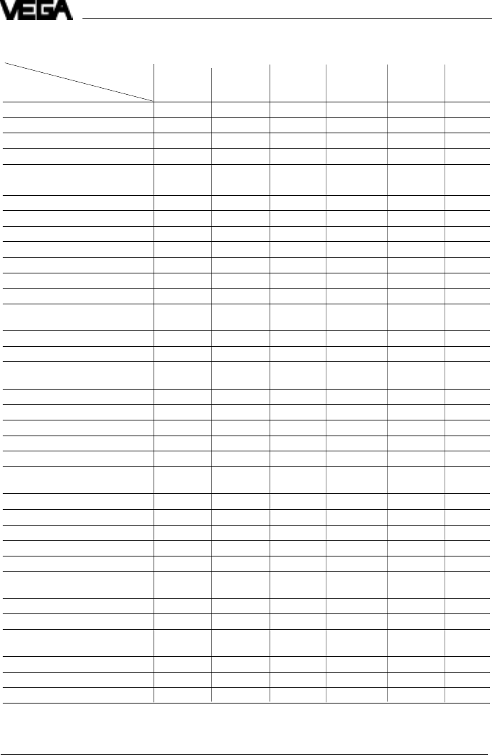
1.2 Types and versions
Type
*)
EK EK EK EK EK EK
Version 11 21 24 26 31 42
Continuous • • • • •
Level detection • • • • • •
Partly insulated • •
Fully insulated • • • •
Oscillators
E 14 • • • •
E 15 • • • •
E 15 Ex • • • •
E 17 • • • •
E 17 Ex • • • •
E 18 ••••••
E 18 Ex • • • • • •
Approvals
CENELEC EEx ia IIC T6 • • • • • •
PTB-Zone 0 EEx ia IIC T6 • • • • • •
Overfill protection
acc. to WHG • • • • • •
German Lloyd
1)
• •••••
Lloyds Register of Shipping
1)
• •••••
American Bureau of Shipping
1)
• •••••
Bureau Veritas
1)
• •••••
RINA
1)
• •••••
Mechanical connection
G
3
/
4
A • •••••
G 1 A • • • • • •
3
/
4
" NPT • • • • • •
1“ NPT • • • • • •
Flange plated • •
Electrode material
Steel • •
StSt •
2)
•
2)
•
3)
•
4)
•
3)
Isolating material
5)
PTFE • • • •
FEP • •
PE • • •