
Owner's manual
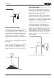
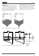
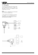
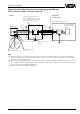
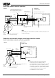
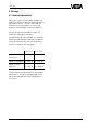
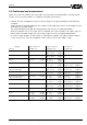
Table Of Contents
- Contents
- Safety information
- Note Ex-area
- 1 Product description
- 1.1 Function and configuration
- 1.3 Technical data
- 1.4 Approvals
- 1.5 Dimensions
- 1.6 Type plate
- 2 Mounting
- 2.1 Mounting instructions
- 3 Electrical connection
- 3.1 Connection instructions
- 3.2 Wiring plan
- 4 Set-up
- 4.1 General adjustment
- 4.2 Level detection
- 4.3 Continuous level measurement
- 5 Diagnosis
- 5.1 Simulation
- 5.2 Maintenance
- 5.3 Repair
- 5.4 Failure removal
Capacitive electrodes EK with signal conditioning instrument 27
Set-up
4 Set-up
4.1 General adjustment
When you state with your order already the
medium to be measured, the electrode will be
adjusted by VEGA. The DK-value and the
conductivity of the medium as well as the
length of the electrode will be considered.
For the set-up the electrode must be ad-
justed with the original medium.
For adjustment of the electrode, the housing
cover must be opened. With the changeover
switch on the oscillator you can choose the
sensitivity range of the electrode.
E14, E15 E17, E18
Stage I 0…25 pF 0…120 pF
(sensitive)
Stage II (standard) 0…100 pF 0…600 pF
Stage III (less
sensitive) 0…400 pF 0…3000 pF
The instruction for adjustment or switch point
adjustment is stated in the operating instruc-
tion of the appropriate signal conditioning
instrument.