
Owner's manual
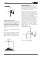
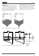
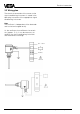
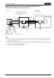
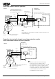
Table Of Contents
- Contents
- Safety information
- Note Ex-area
- 1 Product description
- 1.1 Function and configuration
- 1.3 Technical data
- 1.4 Approvals
- 1.5 Dimensions
- 1.6 Type plate
- 2 Mounting
- 2.1 Mounting instructions
- 3 Electrical connection
- 3.1 Connection instructions
- 3.2 Wiring plan
- 4 Set-up
- 4.1 General adjustment
- 4.2 Level detection
- 4.3 Continuous level measurement
- 5 Diagnosis
- 5.1 Simulation
- 5.2 Maintenance
- 5.3 Repair
- 5.4 Failure removal
Capacitive electrodes EK with signal conditioning instrument 25
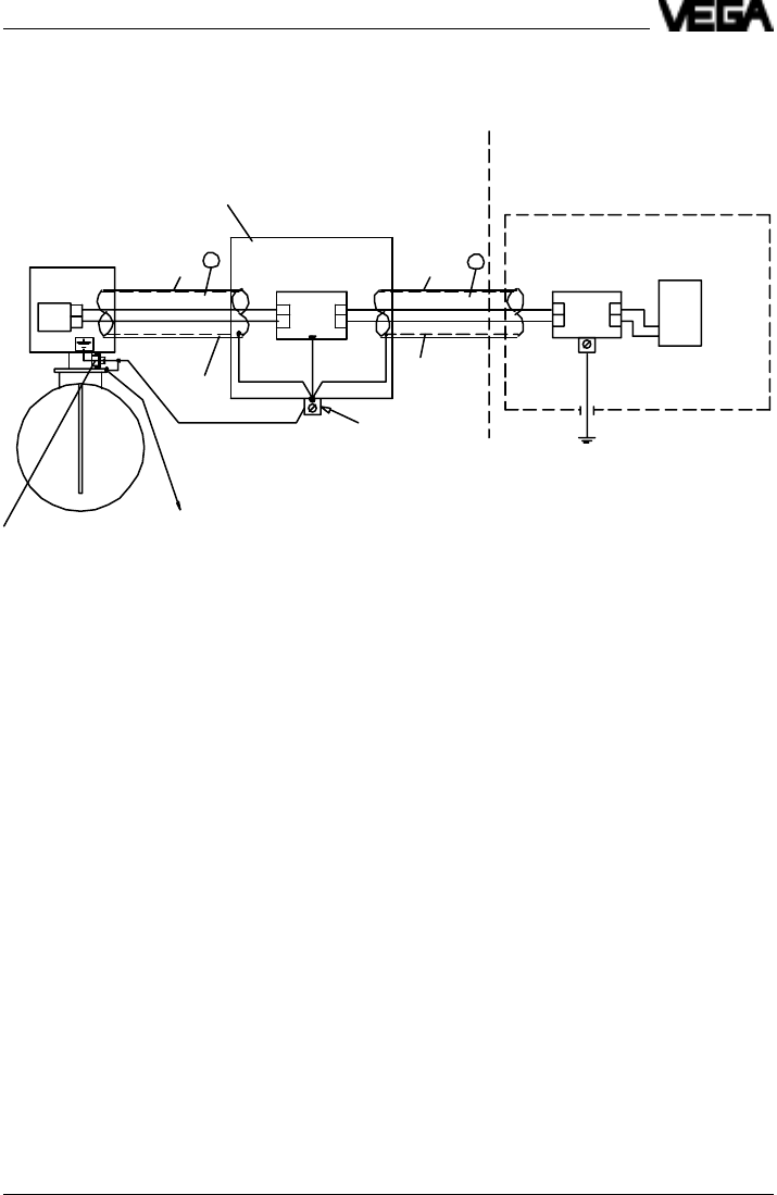
Capacitive electrode with external overvoltage protection unit
Vessel without cathodic corrosion protection
E2
E1
A2
A1
A1
A2E2
E1
1
2
Typ
B62-36G
Typ
B62-36G
B
A
Ex-area
Not-Ex-area
(control room)
optionally overvoltage arrester
optionally overvoltage arrester
B62 - 36 G Ex 0 (metal housing) or
B62 - 36 G Ex (plastic housing)
(L
i
= 0,15 mH, C
i
= 1,5 nF)
Electrode EK
Outer
isolation
Outer
isolation
Screen
Screen
Signal conditioning
instrument or safety
barrier
Earth/ PA-connection
terminal
to potential euqaliza-
tion line
External earth terminal
Note:
[A] Between control room and overvoltage protection system a suitable cable, if necessary a metal cover or
screen, should be used. Screen or metal cover - if necessary - must only be connected to the electrode
side of the overvoltage arrester.
[B] Between overvoltage protection system and capacitive electrode a suitable cable with metal cover, screen
or a suitable cable with metal protection tube should be used (screen, metal cover or protection tube must
be connected to the potential equalisation).
Test voltage of the cable A and B: £ 500 V AC
min. 4 mm
2
Cu
Vessel
Zone 0
Electrical connection