
Owner's manual
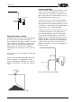
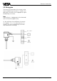
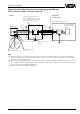
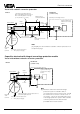
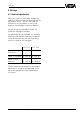
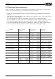
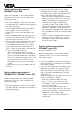
Table Of Contents
- Contents
- Safety information
- Note Ex-area
- 1 Product description
- 1.1 Function and configuration
- 1.3 Technical data
- 1.4 Approvals
- 1.5 Dimensions
- 1.6 Type plate
- 2 Mounting
- 2.1 Mounting instructions
- 3 Electrical connection
- 3.1 Connection instructions
- 3.2 Wiring plan
- 4 Set-up
- 4.1 General adjustment
- 4.2 Level detection
- 4.3 Continuous level measurement
- 5 Diagnosis
- 5.1 Simulation
- 5.2 Maintenance
- 5.3 Repair
- 5.4 Failure removal
24 Capacitive electrodes EK with signal conditioning instrument
3.2 Wiring plan
The electrical connection of the sensor to the
signal conditioning instrument is stated in the
operating instruction of the appropriate signal
conditioning instrument.
Note
The oscillator is independent of the electrode
and can be exchanged locally.
As the oscillators have different characteris-
tics (approx. 5 %), it can be necessary to
readjust the signal conditioning instrument
after electronics exchange.
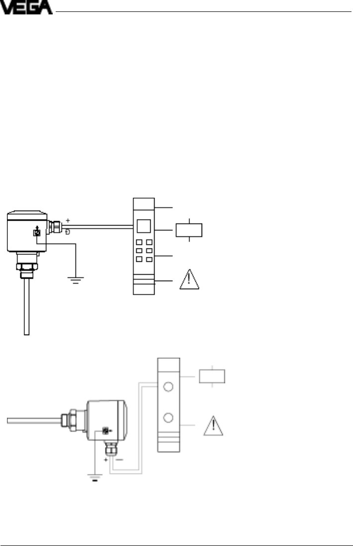
Electrical connection
0/4 … 20 mA
DISBUS