
Owner's manual
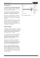
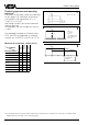
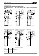
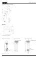
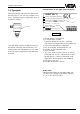
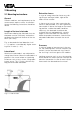
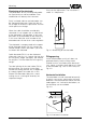
Table Of Contents
- Contents
- Safety information
- Note Ex-area
- 1 Product description
- 1.1 Function and configuration
- 1.3 Technical data
- 1.4 Approvals
- 1.5 Dimensions
- 1.6 Type plate
- 2 Mounting
- 2.1 Mounting instructions
- 3 Electrical connection
- 3.1 Connection instructions
- 3.2 Wiring plan
- 4 Set-up
- 4.1 General adjustment
- 4.2 Level detection
- 4.3 Continuous level measurement
- 5 Diagnosis
- 5.1 Simulation
- 5.2 Maintenance
- 5.3 Repair
- 5.4 Failure removal
Capacitive electrodes EK with signal conditioning instrument 17
Product description
1.6 Type plate
Before mounting and electrical connection
please check if you use the suitable instru-
ment. Therefore note the type plate which is
located as follows:
Type plate
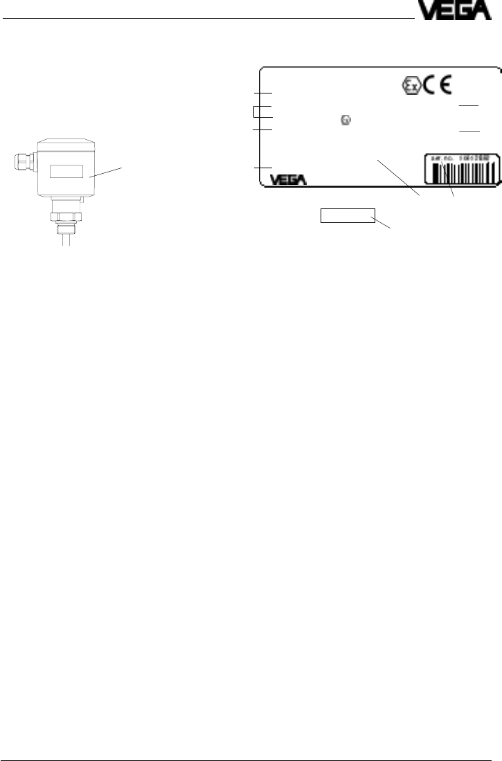
The type plate contains important data re-
quired for mounting and connection. The
configuration and components of the type
plate are hence explained in the following
example.
1 Master data of the order no.
2 Ex-certification number
Explosion protection version - note the
information and regulations of the certificate
3 Data of the electronics / Approvals
4 No. of the order confirmation/Pos.-no.
5 Number of the electrode type
6 Serial number
7 Test mark when used as part of an overfill
protection for vessels storing water endan-
gering liquids - note the information and
regulations of the general type approval
8 Manufacturing year
9 Number of the test authority
Configuration of the type plate (example)
Order code
Detailed information on the order code you
will find in the "Product Information Capaciti-
ve“ or in the "VEGA-Pricelist“.
6
3
1
4
2
5
Z-65.13.XXX
7
VEGA
®
EK 11
type EK11EXO.XGBVSTXXVKXX
see PTB no. EX-98.E.2085 EEx ia IIC T6 0032
PTB 98 ATEX 2086 II 1/2G EEx ia IIC T6
techn. data see document. / certificates 1998
protection: IP 66/67 Insp.
length: 400mm VVO: 02
Ord. no. 123456/000
®
D-77757 Schiltach
8
9