
Owner's manual
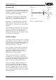
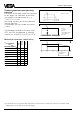
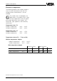
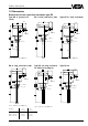
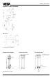
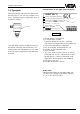
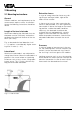
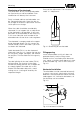
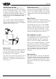
Table Of Contents
- Contents
- Safety information
- Note Ex-area
- 1 Product description
- 1.1 Function and configuration
- 1.3 Technical data
- 1.4 Approvals
- 1.5 Dimensions
- 1.6 Type plate
- 2 Mounting
- 2.1 Mounting instructions
- 3 Electrical connection
- 3.1 Connection instructions
- 3.2 Wiring plan
- 4 Set-up
- 4.1 General adjustment
- 4.2 Level detection
- 4.3 Continuous level measurement
- 5 Diagnosis
- 5.1 Simulation
- 5.2 Maintenance
- 5.3 Repair
- 5.4 Failure removal
Capacitive electrodes EK with signal conditioning instrument 15
Product description
1.5 Dimensions
Type EK 21 (fully insulated)
Type EK 11 (partly insu-
lated)
Type EK 24 (fully insulated,
for adhesive products)
Dimensions of the capacitive electrodes type EK
SW 41
A
B
M20x1,5
32,5
85
G
3
/
4
A
ø14,4
M20x1,5
32,5
85
SW 41
G
3
/
4
A
A
M20x1,5
32,5
85
Isolation A B
outer-ø rod-ø
PE 2,0 mm 14 mm 10 mm
PTFE 2,0 mm 10 mm 6 mm
PTFE 2,0 mm 14 mm 10 mm
L (min. 120 mm, max. 3000 mm)
L (min. 100 mm, max. 3000 mm)
L (min. 100 mm, max. 3000 mm)
EK 11 with concentric tube
SW 41
G
3
/
4
A
EK 21 with concentric tube
L (min. 100 mm, max. 3000 mm)
ø21,3
M20x1,5
32,5
85
SW 41
G
3
/
4
A
ø21,3
M20x1,5
32,5
85
SW 41
G
3
/
4
A
Type EK 26
ø14
M20x1,5
32,5
85
SW 41
G
3
/
4
A