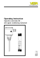
Level and Pressure Operating Instruction Capacitive electrodes EK … with signal conditioning instrument
Safety information Safety information Note Ex-area The described module must only be installed and operated as described in this operating instruction. Please note that other action can cause damage for which VEGA does not take responsibility. Please note the attached approval documents (yellow binder) and especially the included safety data sheet.
Contents Contents Safety information ........................................................................ 2 Note Ex-area ................................................................................ 2 1 Product description 1.1 Function and configuration .................................................. 4 1.2 Types and versions ............................................................. 6 1.3 Technical data ....................................................................... 8 1.4 Approvals ..
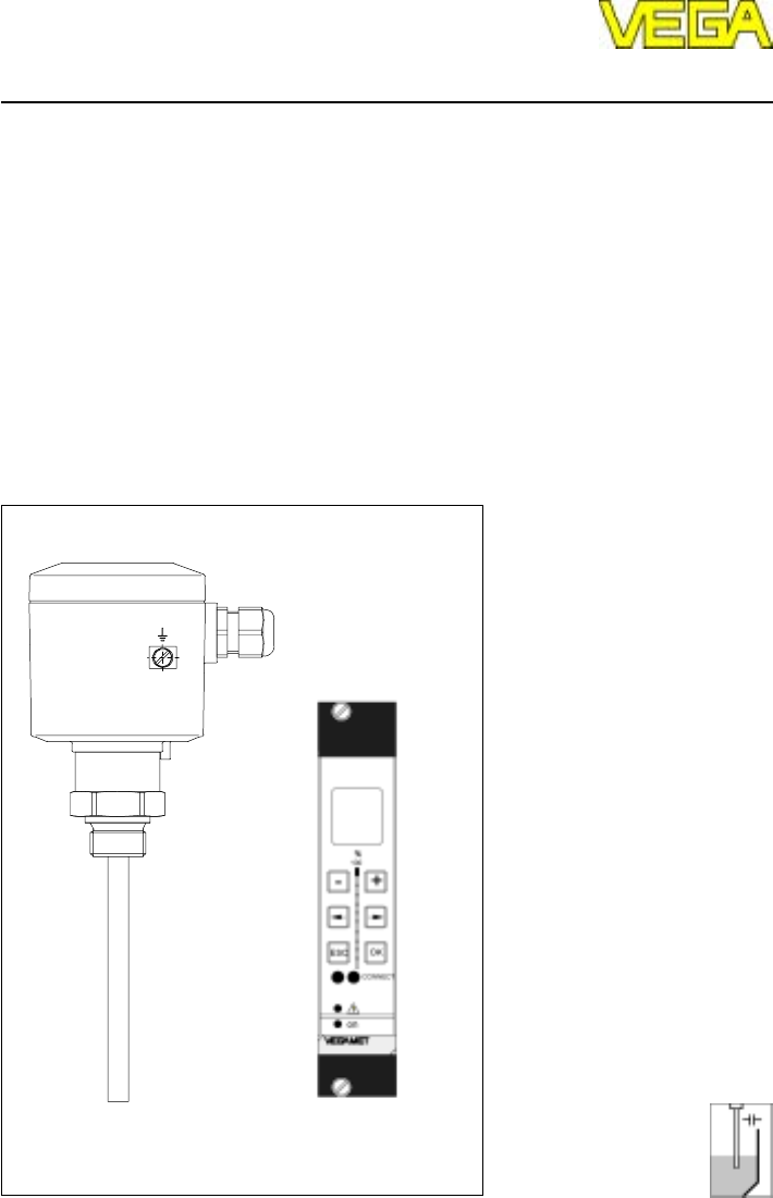
Product description 1 Product description 1.1 Function and configuration Capacitive electrodes series EK detect levels of virtually any medium, unaffected whether liquids, powders, granules or pastes. This is also valid for adhesive mediums. Electrode and vessel wall are the capacitor plates. The medium is the dielectricum. Due to the higher dielectric constant figure (DKvalue) of the medium against air, the capacitance of the capacitor increases with raising covering of the electrode.
Product description The floating signal of the electrode electronics is in the range 4 … 20 mA and can be therefore connected without additional potential separation to other processing systems such as e.g. VEGALOG. In addition to the continuous measurement, also levels can be detected (VEGAMET or VEGAMET + VEGASEL). Level detection Level switches should signal when certain levels are reached, e.g. max. or min. levels. These levels are detected at a fixed point and converted into a switching command.
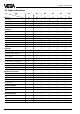
Product description 1.2 Types and versions Type*) EK EK EK EK EK EK Version 11 21 24 26 31 42 Continuous • • • • • Level detection • • • • • Partly insulated • Fully insulated • • • • • • Oscillators E 14 • • • • E 15 • • • • E 15 Ex • • • • E 17 • • • • E 17 Ex • • • • E 18 • • • • • • E 18 Ex • • • • • • CENELEC EEx ia IIC T6 • • • • • • PTB-Zone 0 EEx ia IIC T6 • • • • • • Overfill protection acc.
Product description Type*) EK 26 EK 31 EK 42 • • • • • • • • Plastic (IP 66) • • • • • • Aluminium - plastic coated (IP 66 and 67) • • • • • • • • 7) Version EK 11 EK 21 • • • EK 24 Concentric tube StSt Screening tube (option) StSt Temperature adapter (option) StSt Housing material Others Bending of electrode 6) *) All instrument types also Ex0 1) applied 2) 1.4435 3) 1.4571 4) 1.
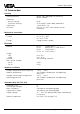
Product description 1.3 Technical data Housing Housing material Protection - plastic housing - Aluminium housing Cable entry Terminals plastic PBT (Polyester) or Aluminium plastic coated IP 66 IP 66 and 67 (meets both protections) 1 pce. M20 x 1,5 for max. 1,5 mm2 cross-section area of conductor Mechanical connection Material Thread Flange 1.4435 (316 L) G 3/4 A or 3/4“ NPT G 1 A or 1“ NPT flange versions, plated Electrode Material Length - rod - cable Isolation Max.
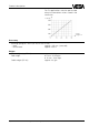
Product description For Ex-applications note the permissible electrical connection values stated in the certificate. Load in W Supply voltage in V Accessory Straining spring of 1.4571 (EK 42, EK 52, EK 53) - load approx. 185 mm (stressed) - tensile load approx. 200 N Weight Basic weight (e.g. EK 24) Rod weight Cable weight (EK 31) approx. 0,8 kg ø 6 mm - 0,23 kg/m ø 10 mm - 0,62 kg/m approx.
Product description Oscillators in two-wire technology for capacitive electrodes EK Type Application Meas. range Frequency E14 Level detection in general I: 0 … 25 pF II: 0 … 100 pF III: 0 … 400 pF 400 kHz VEGATOR VEGALOG E15 Level detection in general with potential separation I: 0 … 25 pF II: 0 … 100 pF III: 0 … 400 pF 400 kHz VEGATOR VEGALOG E15 Ex as E15, however for use in hazardous areas acc.
Product description Oscillator E18 The oscillator E18 with the patented processing (phase selective admittance processing) extends the application range of capacitive level measurement technology. In conjunction with the fully insulated rod electrode EK 24 the oscillator E18 compensates even very conductive build-up. Mounted in an individual rod or cable electrode type EK, E18 ensures also the exact measurement in solids with varying humidity contents.
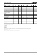
Product description Product temperature and operating pressure1) 1 The figures in the tables relate to the pictures on this page. The statements on pressure are valid for screw connections G 3/4 A, 3 /4“NPT, G 1 A, 1“NPT. With flange versions you have to note their nominal pressure. All electrodes are also suitable for vacuum (-1 bar). EK 21 to 16 bar 2 bar 40 For electrodes certified for Ex-Zone 0 only PTFE and FEP are approved as isolating material acc. to ATEX II 1/2 G EEx ia II C T6.
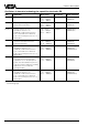
Product description Electronics temperature The following product and ambient temperatures must be maintained so that the limit temperature on the electronics is not exceeded. The stated values are obligatory for applications in hazardous areas. Note for these applications also the appropriate legal documents (test reports, test certificates, type approvals and conformity certificates).
Product description 1.4 Approvals WHG Explosion protection Only certified capacitive electrodes EK**Ex 0 must be used in hazardous areas with combustible gases, vapours or fog. Capacitive electrodes EK**Ex 0 are suitable for the use in hazardous areas of zone 1 and zone 0. Proof for the explosion protection of these instruments is the EC-type approval and the conformity certificate possibly with national zone 0 - annex. These documents are generally attached to the instrument.
Product description 1.5 Dimensions Dimensions of the capacitive electrodes type EK EK 11 with concentric tube Type EK 11 (partly insulated) 85 32,5 85 Type EK 21 (fully insulated) 32,5 32,5 85 M20x1,5 M20x1,5 M20x1,5 SW 41 SW 41 SW 41 G 3 /4 A 3 G /4 A G 3/4 A A A B ø21,3 L (min. 100 mm, max. 3000 mm) EK 21 with concentric tube 85 32,5 L (min. 100 mm, max.
Product description Type EK 31 (partly insulated) SW 41 G 3/ 4 A L (min. 400 mm, max. 20000 mm) Housing Housing of plastic / Aluminium Temperature adapter Concentric tube of 1.4435 Screening tube of 1.4435 with closing cone of PP or PTFE SW 41 ø21,3 Closing cone SW 41 ø21,3 of galvanized steel or 1.
Product description Configuration of the type plate (example) 1.6 Type plate Before mounting and electrical connection please check if you use the suitable instrument. Therefore note the type plate which is located as follows: VEGA® EK 11 1 type EK11EXO.XGBVSTXXVKXX 2 see PTB no. EX-98.E.2085 EEx ia IIC T6 0032 PTB 98 ATEX 2086 II 1/2G EEx ia IIC T6 9 techn. data see document. / certificates protection: IP 66/67 Insp. length: 400mm VVO: 02 Ord. no.
Mounting 2 Mounting Extraction forces 2.1 Mounting instructions In case of strong extraction forces e.g. during filling or settling of solids, high tensile loads can be caused. General Different mediums and requirements to the measurement require various installations. Hence the following instructions should be noted. In these cases use for short measuring distances a rod electrode, as a rod is generally more stable.
Mounting Shortening of the electrode The dimensions of fully insulated electrodes are fixed and must not be modified. Each modification will destroy the instrument. Carry out the adjustment. The instruction is under "4.1 Adjustment“. Partly insulated cable or rod electrodes can be shortened afterwards. Note that due to the change of the basic capacitance also the switch point can change. When the cable should be considerably shortened, it can happen that an adjustment of the electrode is not possible.
Mounting Humidity from outside Aluminium vessels After installation turn the cable entries of horizontally mounted instruments to the bottom to avoid humidity ingress. The instrument housing is rotational by approx. 330°. In case of vertically installed electrodes, loop the connection line to the electrode housing to the bottom so that rain or condensation water can drain off. Use for Aluminium vessels an electrode with steel thread.
Mounting Lateral installation max. 80 mm With electrodes, delivering continuous measured values, the electrode must only be installed vertically. Should the installation from top not be possible, the electrodes can also be mounted laterally (see fig. 2.7) If there are struts or a roof at the installation place of the electrode, you should check if a rod electrode of the requested length can be mounted. If a mounting of the rod electrode is not possible, use a cable electrode. Fig. 2.
Mounting Material cone Note when installing the electrodes into the vessel, that material cones can be caused with solids which can change the switch point. We recommend to choose an installation place where the electrode detects an average value of the material cone. According to the position of the filling and emptying opening in the vessel, the electrode must be installed appropriately.
Electrical connection 3 Electrical connection 3.1 Connection instructions Note Switch off the power supply before starting connection work. The electrical connection must be made dependent on the installed oscillator. The installed electronics type is stated on the type plate of the oscillator. Connect the supply voltage according to the following connection diagrams. Skilled staff Instruments operated in Ex-areas must only be mounted by skilled staff.
Electrical connection 3.2 Wiring plan The electrical connection of the sensor to the signal conditioning instrument is stated in the operating instruction of the appropriate signal conditioning instrument. Note The oscillator is independent of the electrode and can be exchanged locally. As the oscillators have different characteristics (approx. 5 %), it can be necessary to readjust the signal conditioning instrument after electronics exchange.
Electrical connection Capacitive electrode with external overvoltage protection unit Vessel without cathodic corrosion protection Ex-area Not-Ex-area (control room) optionally overvoltage arrester B62 - 36 G Ex 0 (metal housing) or B62 - 36 G Ex (plastic housing) (Li = 0,15 mH, Ci = 1,5 nF) Electrode EK Outer isolation optionally overvoltage arrester Outer isolation B 1 A1 2 A2 Typ B62-36G Signal conditioning instrument or safety barrier A E1 E1 E2 E2 Typ B62-36G A1 A2 Screen Screen mi
Electrical connection Vessel with cathodic corrosion protection Ex-area Not-Ex-area (control room) optionally overvoltage arrester B62 - 36 G Ex 0 (metal housing) or B62 - 36 G Ex (plastic housing) (Li = 0,15 mH, Ci = 1,5 nF) Electrode EK Metal housing mounted earth-free Outer isolation B Outer isolation 1 A1 2 A2 Typ B62-36G optionally overvoltage arrester Signal conditioning instrument or safety barrier A E1 E1 E2 E2 Typ B62-36G A1 A2 Screen Screen min.
Set-up 4 Set-up 4.1 General adjustment When you state with your order already the medium to be measured, the electrode will be adjusted by VEGA. The DK-value and the conductivity of the medium as well as the length of the electrode will be considered. For the set-up the electrode must be adjusted with the original medium. For adjustment of the electrode, the housing cover must be opened. With the changeover switch on the oscillator you can choose the sensitivity range of the electrode.
Set-up 4.2 Level detection Vertically installed electrodes • Set the changeover switch on the oscillator of the electrode to stage I. • Choose the requested mode (A - overfill protection, B - dry run protection) on the signal conditioning instrument. • Fill the vessel to the requested level. • Carry out the adjustment. Turn the potentiometer on the signal conditioning instrument (VEGATOR) very slowly until the signal lamp changes condition.
Set-up 4.3 Continuous level measurement When you state the medium with your order, the oscillator of the electrode is already preadjusted. In this case the medium is stated on the order confirmation. • Choose with the changeover switch on the oscillator the stage according to the following schedule. Take the column corresponding to your medium and choose by means of the length of your electrode the suitable range. The stated lengths partly do not correspond to the actually available electrodes.
Set-up Signal conditioning instrument VEGAMET series 300 When the electrode is not already preadjusted by VEGA, you have to choose the measuring range. • Set the changeover switch on the capacitive electrode EK according to the table on the previous page. • Turn the potentiometer for the full adjustment approx. 22 turns clockwise. • Empty the vessel to the requested min. level. • Turn the potentiometer for the empty adjustment anticlockwise until the pointer of the indicating instrument is at 0.
Diagnosis 5 Diagnosis 5.1 Simulation 5.3 Repair Test switch Due to safety and guarantee reasons repair work beside the wiring must only be made by VEGA-staff. A test switch can be optionally integrated in the housing to simulate a switching condition. By pushing the test switch, an additional capacitance is connected. Just the function of the oscillator and the connected instruments are tested.
Diagnosis 5.4 Failure removal Failure Measure, failure removal The red failureLED of the signal conditioning instrument lights Check the sensor inputs on the following failures: - short-circuit on the input - sensor not correctly connected - sensor line interrupted - supply voltage too low Check if the sensor is connected correctly. - failures on the sensor, effecting a current change below 2 mA or above 23 mA, trigger a fault signal on the signal conditioning instruments.
Diagnosis b.Current value > 22 mA - Check all connections and the connection line to the sensor. - Should the red failure lamp continue to light, separate the sensor from the connection line and connect instead a resistor of 2,2 kOhm. When the failure lamp extinguishes, the sensor is defect. Check the connected sensor. - Should the failure lamp continue to light, connect the sensor again.
Diagnosis Contact 4 against middle pin (1) The resistor must be 1 MW. If the resistor is less, this means humidity in the housing or a failure in the electrode isolation. A possible reason could be a not isolated electrode used in a conductive (humid) medium. If the resistor is higher or if the connection is interrupted, the reason is mainly a bonding failure in the adapter plate or a defect resistor due to strong electrostatic discharge. In both cases return the electrode for repair to VEGA.
Notes Capacitive electrodes EK with signal conditioning instrument 35
VEGA Grieshaber KG Am Hohenstein 113 D-77761 Schiltach Phone (0 78 36) 50 - 0 Fax (0 78 36) 50 - 201 e-mail info@vega-g.de The statements on types, application, use and operating conditions of the sensors and processing systems correspond to the actual knowledge at the date of printing. Technical data subject to alteration 2.22 647 / Nov.