Level and Pressure Operating Instructions Capacitive electrodes EK Profibus PA
Safety information, Note Ex area Safety information Please rfead this manual carefully, and also take note of country-specific installation standards (e.g. the VDE regulations in Germany) as well as all prevailing safety regulations and accident prevention rules. For safety and warranty reasons, any internal work on the instruments, apart from that involved in normal installation and electrical connection, must be carried out only by qualified VEGA personnel.
Contents Contents Safety information ........................................................................ 2 Note Ex area ................................................................................ 2 1 Product description 1.1 Function and configuration .................................................. 4 1.2 Types and versions ............................................................. 5 1.3 Technical data ....................................................................... 7 1.4 Approvals ..
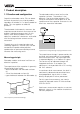
Product description 1 Product description 1.1 Function and configuration Capacitive electrodes series EK can detect the level of practically any kind of product, regardless of whether it is a liquid, powder or paste. This also applies to adhesive products. The electrode and the vessel wall are the capacitor surfaces. The medium is the dielectric. Due to the higher dielectric (DK value) of the medium with respect to air, the capacitance of the capacitor increases as the level rises around the electrode.
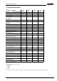
Product description 1.2 Types and versions Type 1) EK 11 EK 21 EK 24 Continuous • • • Partly insulated • Version Fully insulated EK 31 • • • • • • Oscillators CAP E34 PA Ex • • Approvals PTB no. Ex 98.E.2085 • • • • Overfill protection acc.
Product description Type 1) EK 11 EK 21 • • • • • • Plastic(IP 66) • • • • Aluminium - plastic coated (IP 66/IP 67) • • • • Overvoltage protection - option (integrated) • • • • Angled electrode 2) • •3) Version Screening tube (option) stst EK 24 EK 31 Temperature adapter (option) stainless steel (1.4435) Housing material Misc. 1) 2) 3) 6 All instrument types also Ex0 Bending max. 90° EK 21 only in PTFE with 3.
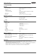
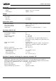
Product description 1.3 Technical data Housing Housing material Protection - plastic housing - Aluminium housing Cable entry Terminals Plastic PBT (Polyester) or Aluminium plastic coated IP 66 IP 66 and 67 (meets requirements of both protection types) 1 piece M20 x 1.5 for max. 1.5 mm2 wire cross-section Mechanical connection Material Thread Flange 1.
Product description Accessory Fixing spring of 1.4571 - length - tensile force approx. 185 mm (strained) approx. 200 N Weight Basic weight (e.g. EK 24) Rod weight - ø 6 mm - ø 10 mm approx. 0.8 kg 0.23 kg/m 0.62 kg/m Connection cables Two-wire sensors Wire cross-section Ground connection Cable entry power supply and signal via one two-wire cable generally 2.5 mm 2 max. 4 mm2 2 x M20 x 1.
Product description Oscillator The oscillator CAP E34 PA Ex with patented processing (phase selective admittance processing) extends the area of application of the capacitive level measurement technology. This function can be switched on, see "4 Setup". If the moisture content goes above 15 % vol., the fully and partly insulated electrodes react differently (see also "1.3 Varying moisture content").
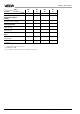
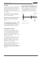
Product description Product temperature 1) and operating pressure 1) 1 bar 40 The numbers in the table all relate to the graphs on this page. The stated pressures are valid for screw connections G ¾ A, ¾" NPT, G 1 A, 1" NPT. When using flanged versions, make sure to note their nominal pressures. All electrodes are also suitable for applications in a vacuum (- 1 bar). EK 21 up to 6 bar 16 0 -30 60 80 ˚C 2 bar 63 EK 24: from 100°C 6 bar, max. 150°C for 30 min.
Product description Electronics temperature Product and ambient temperatures must be kept within the following indicated ranges, so that the limit temperature of the electonics is not exceeded.
Product description 1.4 Approvals CE approval Explosion protection The capacitive electrodes type EK meet the protective regulations of EMVG (89/336/ EWG) and NSR (72/23/EWG). Conformity has been judged acc. to the following standards: Only certified EK** Ex 0 capacitive electrodes may be used in hazardous areas with combustible gases, vapours or fog. Capacitive electrodes EK**Ex 0 are suitable for use in hazardous areas of zone 1 and zone 0.
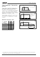
Product description 1.5 Dimensions Dimensions of the capacitive electrodes type EK … Ex 0 Type EK 11 (partly insulated) 85 32,5 32,5 85 90 90 35 35 G¾A G1 A SW 41 G¾A G1 A 20 G¾A G1 A M20x1,5 SW 41 20 20 SW 41 50 32,5 M20x1,5 M20x1,5 35 Typ EK 21 (fully insulated) 90 85 EK 11 with concentric tube A L L L A B Ø 21,3 L (min. 100 mm, max. 3000 mm) L (min. 100 mm, max.
Product description Housing Temperature adapter 85 32,5 133 90 SW 41 M20x1,5 SW 41 20 housing of plastic/Aluminium G ¾ A, G1A of 1.4435 Concentric tube of 1.4435 Screening tube of 1.
Product description Contents of the type plate (example) 1.6 Type plate Before mounting and electrical connection, please make sure you are using a suitable instrument. Note the type plate which is located as shown below: 1 2 2 3 4 VEGA® EK 11 type EK11EXO.XGBVSTXXVKXX see PTB Nr. EX-98.E.2085 EEx ia IIC T6 0032 PTB 98 ATEX 2086 II 1/2G EEx ia IIC T6 techn. data see document. / certificates 1998 protection: IP 66/67 Insp. ser. no. 10612892 length: 400mm VVO: 02 Ord. no.
Mounting 2 Mounting 2.1 Mounting instructions General Different mediums and measurement requirements make different installation positions necessary. Please note the following points. Lateral load Make sure that the electrode is not subjected to strong lateral forces. Mount the electrode in a position in the vessel where no disturbing factors such as e.g. stirrers, filling openings etc. are present. This is especially important for very long rod and cable electrodes.
Mounting To avoid fraying the steel cable (EK 31) during cutting, you must tin the cable around the cutting position with a soldering iron or blowtorch, or tightly wrap the cable with a wire. Shorten the electrode cable with a metal cutting saw or a cutting-off wheel by the requested length. This is mainly valid for outdoor mounting, in areas where high humidity is expected (e.g. from cleaning processes) or for cooled or heated vessels. Carry out an adjustment. The instruction is under "4.1 Adjustment".
Mounting Non-conductive vessel In non-conductive vessels, e.g. plastic tanks, the second pole of the capacitor must be provided separately, e.g. in the form of a concentric tube. When using a standard instrument, a suitable grounding surface is necessary. Provide therefore the largest possible grounding surface, e.g. wire braiding laminated into the vessel wall or metal foil glued to the vessel. Connect the grounding surface to the ground terminal on the housing.
Mounting The meas. probe must be installed in a way that takes the filling and emptying apertures of the vessel into account. To compensate meas. errors caused by the conical heap, you should install the electrode at a distance of approx. d/6 from the vessel wall. Material cone When installing the meas. probe in a vessel, be aware that conical heaps which alter the switching point can form in solid materials.
Electrical connection 3 Electrical connection 3.1 Connection instructions Note Switch off the power supply before starting connection work. Connect the supply voltage acc. to the following connection diagrams. - Screened cable is recommended for connection (cable types, see chapter "1.3 Technical data"). The shielding must be connected on both ends (on the T-adapter and on the instrument). - For use in Ex areas, the installation regulations must be noted. 3.
Electrical connection Wiring the indicating instrument VEGADIS 50 Loosen the 4 screws of the housing cover on VEGADIS 50. To make wiring easier, we recommend fastening (with a screw) the cover to the side of the housing during connection work. Adjustment module Tank 1 m (d) 12.
Electrical connection Qualified personnel Instruments which are operated in Ex areas must only be connected by qualified personnel. they have to note the installation regulations and attached EC type approval certificates and conformity certificates. If the capacitive electrodes are to be mounted on vessels which must be protected against ignition by lightning strokes (acc. to TRbF 100 no. 8, para.
Electrical connection Profibus PA in Ex environment For application in Ex areas, the PA bus and all connected instruments must be certified as intrinsically safe protective class "i". Fourwire instruments requiring a separate supply must at least have an intrinsically safe PA connection. VEGA sensors for PA-Ex environment are always "ia two-wire instruments". In the so-called Fieldbus Intrinsically Safe Concept (FISCO), the general conditions for an Ex safe bus configuration have been laid down.
Electrical connection Electrical data of the cables RDC no. of A in cores mm 2 Z31.25kHz C in nF/km damping screen 44 Ω/km 2 0.75 100 Ω +/- 20 Ω < 90 < 3 dB/km 39 kHz Cu-braiding SINEC L26XV1 44 Ω/km 830-35H10 (Siemens) 2 0.75 100 Ω +/- 20 Ω < 90 < 3 dB/km 39 kHz Cu-braiding 2 0.32 150 Ω 29.
Electrical connection Overvoltage arrester for Ex systems The unit B62-30W can be used as overvoltage arrester in Ex systems. In the Ex area, the overvoltage arresters must only be installed in zone 1 and 2 (not zone 0). You must differentiate between overvoltage protection of intrinsically safe and non intrinsically safe circuits. For Ex systems, please note the installation regulations and the special prerequisites cited in the respective conformity certificates. B62-30 W: 9 … 36 V DC, max. 1 A e.g.
Electrical connection Wiring example for the installation of an Ex system on vessels without cathodic corrosion protection The following overvoltage arrester can be used: - B62-30 W: 9 … 36 V DC, max.
Electrical connection Wiring example for the installation of an Ex system on vessels with cathodic corrosion protection. The following overvoltage arrester can be used: - B62-30 W: 9 … 36 V DC, max.
Setup 4 Setup 4.1 Adjustment media All VEGA Profibus sensors operate in profile 3 and can be adjusted with: - the adjustment program VVO on a PC with Profibus card - VVO via VEGACONNECT 3 - the adjustment program PACTwareTM, under which VVO runs as a subprogram - Siemens-Software PDM in conjunction with an EDD (Electronic Device Description) - the adjustment module MINICOM in the sensor. Adjustment with VVO on the PC The adjustment program VVO enables userfriendly ajustment of VEGA Profibus PA sensors.
Setup If all sensors are already connected to the bus line, the address must be adjusted via VEGACONNECT 3, the adjustment module MINICOM or via the mini coding switch. Example: To select address 37, set switch 1 (value 1), switch 3 (value 4) and switch 6 (value 32) to position "on". Set all other switches to position "off". Adjustment with PACTwareTM The adjustment with PACTwareTM corresponds to VVO adjustment, in which case, VVO runs as a subprogram of PACTwareTM.
Setup 4.2 Adjustment with the adjustment module MINICOM As with the PC, the sensor can also be adjusted with the small detachable adjustment module MINICOM. The adjustment module is inserted into the sensor or into the external indicating instrument (optional). Adjustment elements The adjustment module MINICOM is menudriven. The clear text indications on the display lead through the menu. The functions of the keys are described in the following. 3 2 1 - Tank 1 m (d) 12.345 Tank 1 m (d) 12.
Setup Arrow keys (5) With the keys > and <, you can move within the menu level from one menu item to the other. Digital indication (1) On the digital indication, the actual measured value is displayed during operation. When you adjust the instrument, the clear text indication displays the appropriate function. ▼ Branching point from which you can change to a lower menu. ▼ ▼ This symbol informs you about an ensuing safety enquiry.
Setup Application: - highly conductive products - adhesive, conductive products - solids with fluctuating moisture content. For use in conductive, viscous liquids, a suitable electrode of type EK 24 or EL 24 should be used. 2. Adjustment Under the menu item "Adjustment" you inform the sensor of the meas. span it should operate in. Max. 100 % corresponds to 1200 l Span Min. The following criteria apply to conductivity: with conc.tube wo.conc.
Setup Key Display Sensor m(d) 4.700 OK OK OK OK Parameter adjustment Adjustment with medium Min. adjust at % ------(Min. adjustment) 3. Conditioning Under the menu item "Conditioning" you can scale the display, set an integration time and choose a linearisation curve. Scaling Here, you can scale the digital display of the electrode. 0 % correspond Here, you enter the value which should be displayed when 0 % level is reached, e.g. 20 l.
Setup Menu schematic of the adjustment module MINICOM 1. Parameter Sensor optimise Mode 1 Configuration Add’l functions Info 1) Sensor Tag Sensor Tag Adjustment Electrode type No. 01 Sensor type CAP E34 Serial number Softw. Vers. Sensor addr. 0% corres ponds XXXX w.out medium Max. adjust at % XXX.X Adjust ment in pF Offset correc tion pF Capacitance pF/m 3. Signal condit ioning Scaling Min. adjust at % XXX.X Offset Sensor addr. 2. with medium max.
Setup Reset Total Reset Basic reset Total Reset Lan guage Eng lish DKmeasure ment Immersion 3) 3) OK? Basic reset OK Reset Now ! OK ? Reset Now! 4. Outputs Simulation PA output Prop. to volume Sensor display Failure mode Error value DKmeas. Now! OK? DK value (Er) 3) 3) OK ? Simulation Now! OK? Simulation in V% XXX.X Prop. to Percent With these keys you move in the menu field to the left, to the right, top and bottom. ESC act. dist.
Setup 4.3 Adjustment with VVO VVO connection to the bus cable If the oscillator CAP E34 PA Ex is installed, the electrode can also be adjusted via a PC with the adjustment software VVO (from version 2.30). You need a Profibus DP interface card (from Softing) in your PC in order to adjust the sensor with the adjustment software VVO. This card must be used to make the connection between computer and Profibus DP cable (a direct connection or a connection to the Profibus PA cable is not possible).
Setup • Switch on the power supply of the connected sensor. • Start the adjustment software VVO (VEGA visual Operating) on your PC. • In the entrance screen, you choose with the arrow keys or the mouse the item Planning and click to OK. You should only choose Planning if you are authorised to modify the instrument parameters. Otherwise choose Operator or Maintenance. In the window "User identification", you are asked for the name and the password.
Setup Under the menu item "Configuration", you can choose the following functions: • Measuring system • Measurement loop • Program The electrode is already preset at VEGA. The measuring system must only be reconfigured if the oscillator is exchanged. Profibus PA address In this window, you can assign a bus address to the sensor in the field "Sensor address". This function is only available if the mini coding switch on the oscillator is set to 126 or higher.
Setup Configuration of measurement loops Click to Configuraiton, point to Measurement loop, then click to Modify. Measurement loop description In this field, you can give your measurement loop a descriptive label, e.g. level measurement - cleaning detergent. Up to 80 characters can be entered. The measurement loop description is not saved in the sensor but on the PC. Application For capacitive electrodes, "Level measurement" is permanently set and cannot be modified.
Setup Options In this function, program settings such as backup, etc., are available. Instrument data Display Diagnostics Instrument data Configuration Services Quit Help From the window "Instrument data parameter adjustment", you can reach all submenus of the sensor. Just test the various buttons one after the other. You will always return to this window. Click to the button Adjustment to carry out the adjustment.
Setup Attention! Please do not confuse this offset with the offset correction (instrument data/ parameter adjustment/additional functions). Under certain circumstances, an adjustment can also be carried out without medium with the help of the processing software VVO. The requirements for an adjustment in m are: Adjustment with medium Min. adjustment There must be min. level in the vessel. If you push the button Save, the output is set to the entered percentage value. For example.
Setup If you have chosen pF, you can assign a corresponding value in pF to the percentage value. Example 0 % = 97,2 pF 100 % = 1428.0 pF The values for the adjustment will be accepted by pushing the button OK.
Setup Push the button Transfer to call up further linearisation curves. Click in the window "Conditioning" to Integration time. In the window "Linearisation", you can choose the linearisation curves of a horizontal cylindrical tank or a spherical tank. If you choose a user-programmable curve, you can then click to Edit and open the program "Tank Calculation". With this program, you can calculate the curves of different tank forms (see the manual "VEGA Visual Operating").
Setup Click in the window "Outputs" to Profibus output. Sensor parameter adjustment - Sensor optimisation In this window, the mode of the sensor can be set. With this, you modify the phase angle of the phase selective admittance processing (PSA). "Mode 1" is preset. In the window "Profibus output", you can determine the options for Profibus output (acc. to Profibus PA instrument profile). Confirm the settings with OK.
Setup Sensor parameter adjustment - Offset correction Confirm the question with OK, if the conditions are met. This function is necessary if an adjustment should be carried out in m. With this function, the initial capacitance is saved in the electronics. A prerequisite is that the electrode is installed in the vessel and completely unimmersed. An offset correction is only necessary if adjustment without medium is to be carried out.
Setup Diagnostics Display Diagnostics Instrument data Configuration Services Quit Help Status Simulation Under the menu item "Diagnostics", you can choose the following functions: • Status • Simulation Status This function is not available. Choose the requested measurement loop and click to OK. Simulation With this function, you can simulate a certain level. Push the start button to activate the simulation. Shift the scrollbar to the requested PA output value or enter a specific PA output value.
Setup Select the requested measurement loop and click to OK. Under the menu item "Services" you can select the following functions: • Print • View • Backup • Restore configuration • Edit database • User level • Connection • Modem In the window "Simulation of outputs", you click to Start, to start the simulation. With the buttons "<–" and "–>" (or with the slide switch) you can set values between -10 % and 110 %. To quit the simulation, click to Stop.
Setup Operator This user level is for the operator. In this level, you can have the measured value displayed and the sensor data printed. There is no password required for this level. Maintenance If you select the level Maintenance, all functions are available except configuration. The password for this level is: VEGA. Planning If you select the level Planning, all functions are accessible. The passwords for the planning level are: VEGA - VEGA.
Diagnostics 5 Diagnostics 5.1 Simulation 5.3 Repair To simulate a certain filling level, you can call up the function Simulation in the oscillator or in the adjustment program VVO. You hereby simulate a certain current. Remember that connected instruments, such as e.g. a PLC, react according to their settings and that alarms may be triggered or system functions activated. Repair work requires opening the instrument to correct defects.
Diagnostics 5.4 Failure rectification Failure Measure, failure rectification Sensor defective, measurement does not react to level changes Test the internal connections: • Loosen the 4 screws of the housing cover with a Phillips screwdriver and remove the housing cover. • Loosen the two small screws with a Phillips screwdriver and pull the oscillator out of the housing.
Diagnostics Failure Measure, failure rectification Contact 4 and vessel The connection between contact 4 and the metal vessel (not instrument hexagon or electrode flange) should be as good as possible. Measure with an ohmmeter (range very low) the resistance value between contact 4 and the vessel.
Notes Failure Measure, failure rectification Error message Adjustment span too small E017 Increase the span between empty and full adjustment. Error message General Instrument error E034 PA status 12 Instrument error An error in the sensor was found. Posible causes are: - supply voltage not within tolerance - defective oscillator - damage to the electrode or to the insulation - electrode short-circuited against vessel wall • Separate the sensor from power supply and then reconnect (cold start).
Notes Capacitive electrodes EK - Profibus PA 53
Notes 54 Capacitive electrodes EK - Profibus PA
Notes Capacitive electrodes EK - Profibus PA 55
VEGA Grieshaber KG Am Hohenstein 113 D-77761 Schiltach Phone (07836) 50-0 Fax (07836) 50-201 E-Mail info@de.vega.com www.vega.com ISO 9001 All statements relating to scope of delivery, application, practical use and operating conditions of the sensors and processing systems correspond to the latest information at the time of printing. Technical data subject to alterations 2.