
Manual


5 Setup
5.1 Setup
Proceed as
follows for a fresh adjustment:
3
4
5
6
1
2
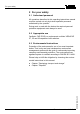
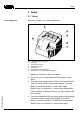
Fig. 1: Oscillator with relay output
1 Type label
2 Connection terminals
3 Tensile proving ring
4 Control lamp
5 DIL switch for mode adjustment
6 Potentiometer for switching point adaptation
1 Make sure that the probe is uncovered.
2 Pierce the cover of the potentiometer (6) with a screw-
driver.
3 Turn the below potentiometer (6) first of all anticlockwise
(max. 20 turns) until the control lamp signals "covered".
Mode A (overfill protection) = control lamp lights
Mode B (dry run protection) = control lamp extinguishes
If this condition is already reached, you can continue with
the next step.
4 Turn the potentiometer (6) very slowly (due to the damping)
clockwise until the control lamp signals "uncovered".
Mode A (overfill protection) = control lamp extinguishes
Mode B (dry run protection) = control lamp lights
Fresh adjustment
Electronics module - CAP E31R 9
Setup
33761-EN-070809