
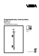
User Manual
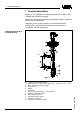


1
2
B
A
4
(1,056)
3
(0,793)
2
(0,528)
1
(0,264)
5
(1,321)
6
(1,585)
7
(1,849)
8
(2,113)
2500 (98
7
/
16
")
3000 (118
1
/
8
")
2000 (78
3
/
4
")
1500 (59
1
/
16
")
500
(19
5
/
8
")
1000 (39
3
/
8
")
0%
100%
0
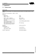
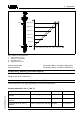
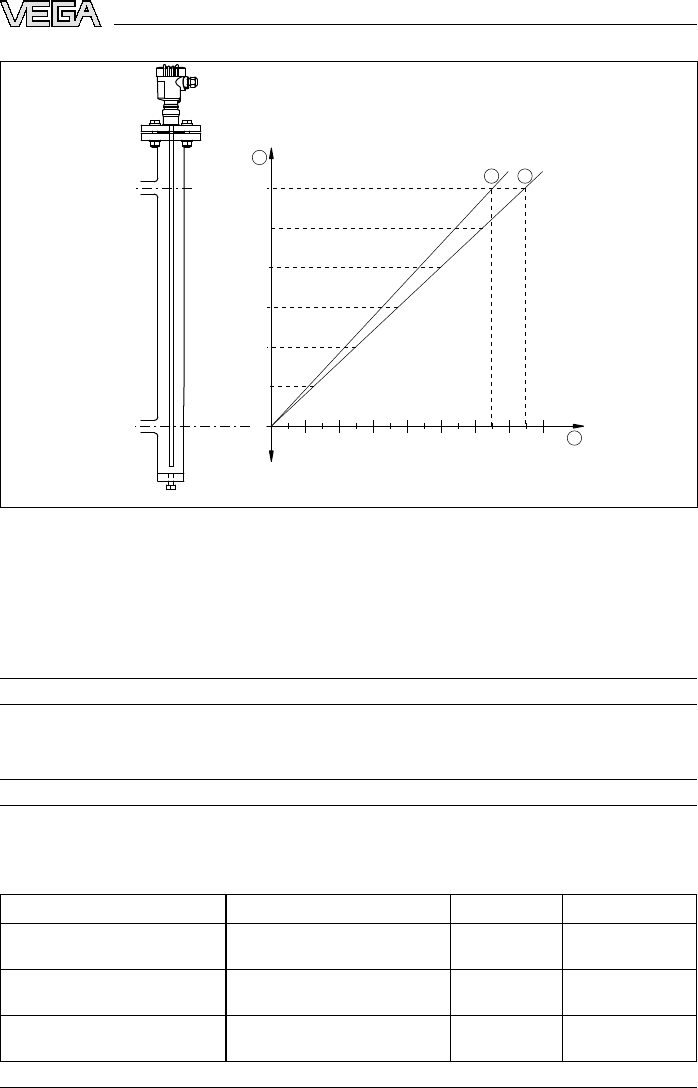
Fig. 2: Volume
of the bypass tube
1 Tube length in mm (in)
2 Volume in L (US.liq.gal)
A Standard version
B High pressure version
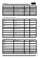
Process temperature see process fitting - connection flange (B,C)
Process pressure see process fitting - connection flange (B,C)
Process fitting - Measuring instrument flange (A)
DN 50 PN 40, Form C, DIN 2501
Flange 2" 300 lb RF, ANSI B16.5
Process fitting - connection flange top/bottom (B, C)
Process pressure in bar (psig) depending on the process temperature
Process temperature 150 °C (302 °F)
Flanges Process pressure Seal Wall thickness
Flange DN 20 PN 40, Form C,
DIN 2501
12 bar (174 psig)/31 bar (450 psig) Klingersil 2 mm (0.079 in)
Flange DN 25 PN 40, Form C,
DIN 2501
12 bar (174 psig)/31 bar (450 psig) Klingersil 2 mm (0.079 in)
Flange DN 50 PN 40, Form C,
DIN 2501
12 bar (174 psig)/31 bar (450 psig) Klingersil 2 mm (0.079 in)
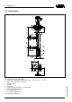
Bypass 72 • with VEGAFLEX level
sensor 5
3 Sup
plement
33545-EN-081216