
Instruction Manual


Carrier BGT 596, 596 Ex.M 5
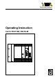
Operating instruction
BGT 596 Ex.M
Mechanical data
Dimensions W x H x D = 482,6 (19“) x 132,5 x 254
Module positions choice out of 84 positions
Connection for protector tongue 2-fold, 2 x 6,3 x 0,8
Blind cover 4 TE (4 x 5,08 = 20,32 mm)
Covers (top and bottom) screwed with the basic carrier
Protective measures
Wiring side IP 00
Upper and lower side IP 20
Front side (completely equipped) IP 30
Ex-module (consisting of)
Guide rails 2 pcs.
Instrument coded key 2 pcs.
Fixing screw 2 pcs. M2,5
Separating chamber 1 pce. with integral nut
Multipoint connector with Ex-coded key 1 pce.
- type DIN 41 612, series F, 32-/33-pole, d, b, z
- connection see the following list
Wire-Wrap 1,0 x 1,0 mm Article no. Module- Ex-33 A Ex-32 A Ex-33 SA
Plug 2,8 x 0,8 mm Ex-33 B –– Ex-33 SB
Termi-Point 1,6 x 0,8 mm Ex-33 C Ex-32 C Ex-33 SC
Soldering connection Ex-33 D Ex-32 D Ex-33 SD
Screw connection Ex-33 E –– ––
Connection for signal conditioning VEGATOR 536 Ex 526 W Ex 534 Ex
instruments 537 Ex
VEGATOR 532 Ex 535 Ex
VEGATOR 521 Ex
522 Ex
523 Ex
527 Ex
VEGAMET 513 Ex 509 Z Ex
514 Ex
514 D Ex
515 Ex
VEGATRENN 544 Ex
546
547 Ex
548 Ex
VEGASTAB 593-60, 593 and 594 see BGT 596