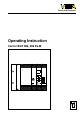
Level and Pressure Operating Instruction Carrier BGT 596, 596 Ex.M – + – – 5 9 OK ESC 0 1 10 0 max. + + – – 0 min.
Operating instruction Contents Safety information ......................................................................... 2 1 Product description 1.1 Function and configuration ................................................... 3 1.2 Types and versions ............................................................... 3 1.3 Technical data ....................................................................... 4 1.4 Dimensions ...........................................................................
Operating instruction 1 Product description 1.1 Function and configuration The carrier BGT 596 or BGT 596 Ex.M is provided for signal conditioning instruments and electronics units of series 500 which are designed in 19“-technology (European size DIN 41 494). It is designed for installation into a 19“-rack or into a switching cabinet with 19“-frame. Configuration The supporting elements of the carrier are made of eloxated Aluminium.
Operating instruction 1.
Operating instruction BGT 596 Ex.
Operating instruction 1.4 Dimensions 19" = 482,6 4 254 465 132,5 57,1 7,5 10,5 84 TE = 426,72 2 Mounting 2.1 Coding 2.2 Module position A mechanical instrument coding by means of a pin in the multipoint connector and a hole in the multiple plug ensures that by interchanging the module card only the correct card type can be inserted again. The pin (attached) is supplied with the module and must be inserted into the hole of the card specific position when mounting the module.
Operating instruction 2.3 Mounting Mounting steps BGT 596 Step 1 Except this operating instruction (BA) the BAs of the installed module cards have to be observed. The mounting of the module cards must start directly after the blind cover mounted on the left (4 TE = air gap to the side wall of the carrier of ≥ 10 mm). BGT 596 Ex.M The instructions and mounting steps described in the following are part of the explosion protection and must be maintained exactly.
Operating instruction Step 3 Step 4 Relating to BGT 596 Connect the lines Relating to BGT 596 Ex Shift the separating chamber up to the multipoint connector and fasten with the integral nut on the penetrating fixing screw of the multipoint connector.