
Installation manual


Série 32 Mlift Vector - Prog.Vectorielle Installation manual Chapter III - page 2
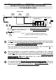
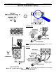
CONNECTING OF MACHINE ROOM
Thermostat
Motor
thermo-contact
Safety
indicator
In use
indicator
Fault
Bridge
Phase
fail
TCS
GM
GD MAN/
* OPTION
*
24V / 1,2W
KC22
Main board
VEC01
+24 CAI CBI0V
Brake
Input voltage
220 or 380 V
Traction
Motor
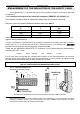
L1
L2
L3
N
L1 L2 L3
-BR+BR
1311 12
M
3~
3 PHASE
NETWORK
CURRENT
L1 L2 L3
PE
L1' L2' L3'
PE
L3P
L2P
L1P
PE
(bottom)
MAIN BOARD BG15
Incremental
encoder
INCREMENTAL ENCODER
HENGSTLER
+24
0V
CAI
CBI
WHITE
GREEN
BLACK
RED
Cut the wires which are not used.
Screening cable do not connect.
Wires CAI and CBI should be crossed
in dependance of your configuration.
FILTER
Screened
Cable
BH08
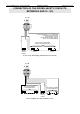
θ
L1L3 L2
RAIL
ELECTROMECHANICAL
RAIL
ELECTROMECHANICAL
K62 KM11 KM12 KM17
control
of the ventilation
Thermal
departure
Delayed
PH THV0V STH 0V CLSUSD DEF 24R GD MAN 0VGM MTH 0V
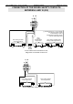
L2P
L1P
L3P
KT1
L2P
L1P
KT2
+19.5V
-19.5V
BG22
KT2
+19 V
-19 V