
Installation manual


Série 32 Mlift Vector - Prog.Vectorielle Installation manual Chapter II - page 3
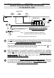
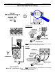
INSTRUCTION FOR CONNECTING ANY DEVICES
TO THE SAFETY LANE
RSCV
PE
0 V
Protection
CV & RS : HINGED TERMINALS TO TEST THE
INSULATION OF THE SAFETY LANE
250 V
SAFETY LANE
2 SEPARATE WIRES
MAKE SURE THAT ALL OF THE TERMINALS
ARE CORRECTLY TIGHTENED !
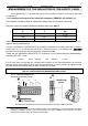
1
2
3
DOOR
CLOSED
CONTACTS
PRIMARY
SAFETY
DOOR
LOCKED
CONTACTS
Note : To make this diagram clearer, the electronic
interfaces and the controller have been omitted.
(BG15 Main board)
2
1068
6
8
10
R
R
R
Relays
(K30)
Contactors
RS
RS
CONTACTS
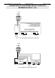
Connection of the interfaces to he lift’s safety lane
1
The 0 V of the secondary winding of the transformer which powers the safety
lane must only be connected to the CV hinged terminal, by a wire whose
the colour is neither green and yellow, nor blue.
Only the hinged terminal mentioned above should carry the label CV; no
other terminal in the controller should have this label.
2
With the exception of movement contactors (connected to the controller
relays) ALL devices (contactors, electronic interfaces) with a pole connected
to the safety lane, must have their other pole connected uniquely to the RS
hinged terminal (R
eference Securities), by a wire whose the colour is
neither green and yellow, nor blue.
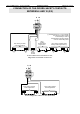
3
The hinged terminals RS and CV must never be wired together; they must
be linked to the protection conductor PE by 2 separate wires, whose
colours must be neither green and yellow, nor blue.