
Installation manual


Série 32 Mlift Vector - Prog.Vectorielle Installation manual Chapter VII - page 92
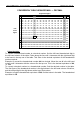
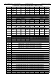
OUTPUTS DEFINITIONS
• Ram Address
IF
:
best displayed in segment mode.
Segment
0
to
7
:
POS0-7
(Positioning 0 to 7) (S ELEC).
They show us respectively the state of the Positioning Outputs POS0 to POS7.
The corresponding segments are on when the Outputs are activated and give out 0 Volts.
The corresponding segments are off when the Outputs are de-activated and give out 24
Volts.
• Ram Address
20
:
best displayed in segment mode.
Segment
0
to
7
:
POS8-15
(Positioning 8 to 15) (S ELEC).
They show us respectively the state of the Positioning Outputs POS8 to POS15.
• Ram Address
61
:
best displayed in segment mode.
Segment
7
:
V4
(Valve 4) (S CONT).
This shows us the state of Valve Relay 4.
Segment 7 is on when Valve Relay 4 is fed in order to drive Valve 4.
Segment 7 is out in the reverse case.
Segment
6
:
V3
(Valve 3) (S CONT).
This shows us the state of Valve Relay 3.
Segment 6 is on when Valve Relay 3 is fed in order to drive Valve 3.
Segment 6 is off in the reverse case.
Segment
5
:
V2
(Valve 2) (S CONT).
This shows us the state of Valve Relay 2.
Segment 5 is on when the Valve Relay 2 is fed in order to drive Valve 2.
Segment 5 is off in the reverse case.
Segment
4
:
V1
(Valve 1) (S CONT).
This shows us the state of Valve Relay 1.
Segment 4 is on when Valve Relay 1 is fed in order to drive Valve 1.
Segment 4 is off in the reverse case.
Segment
3
:
Not used
Segment
2
:
L
(Line Relay) (S CONT).
This shows us the state of the Line Relay (L).
Segment 2 is on if Relay L is fed.
Segment 2 is off in the reverse case.