
Installation manual


Série 32 Mlift Vector - Prog.Vectorielle Installation manual Chapter VII - page 88
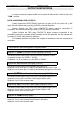
OUTPUTS DEFINITIONS
Segment
2
:
GV/PV
(Fast Speed / Slow Speed relay) (S CONT),
or
V2
(for Freq.Drive).
This shows us the state of the Fast Speed / Slow Speed Relay (GV / GP).
Segment 2 is on if relay GV / PV is supplied to command contactor GV.
Segment 2 is off if the relay GV / PV is not supplied to command contactor PV.
Segment
1
:
DE
(Down Relay) (S CONT).
This shows us the state of the Down Relay (DE).
Segment 1 is on if the DE relay is fed.
Segment 1 is off in the reverse case.
Segment
0
:
MO
(Up Relay) (S CONT).
This shows us the state of the Up Relay (MO).
Segment 0 is on if the MO relay is fed.
Segment 0 is off in the reverse case.
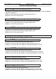
• Ram Address
14
:
best displayed in segment mode.
Segment
7
:
V1
(Speed 1) (S ELEC).
This shows us the state of Speed 1 output.
Segment 7 is on if Speed 1 output is activated.
Segment 7 is off in the reverse case.
Segment
6
:
V0
(Speed 0) (S ELEC).
This shows us the state of the Speed 0 output.
Segment 6 is on if Speed 0 output is activated.
Segment 6 is off in the reverse case.
Segment
5
:
Not used.
Segment
4
:
SH8
(Bridge 8) (S ELEC).
This gives us the state of the SH8 output.
Segment 4 is on when SH8 output is activated and gives 0 V.
Segment 4 is off in the reverse case.
Segment
3
:
INH2
(Rear Door Inhibition) (S ELEC).
This shows us the state of the INH2 output which is activated when the anti-skating
integrator is dropped.
Segment 3 is on when INH2 output is activated and gives 0 V.
Segment 3 is off in the reverse case.