
Installation manual


Série 32 Mlift Vector - Prog.Vectorielle Installation manual Chapter VII - page 77
INPUTS DEFINITIONS
In order to make the inputs visible, we must put the little switch on the left up in the
" RAM " position.
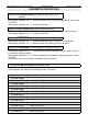
• Ram Address
00
:
best displayed in segment mode.
Segments
0
to
7
:
C0 - 7
(Car Calls 0 to 7).
They indicate to us respectively the state of the car call contacts C0 to C7 with the
common COMB button.
The corresponding segments are on when contacts are closed to make a call.
The corresponding segments are off in the reverse case.
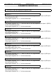
• Ram Address
01
:
best displayed in segment mode.
Segments
0
to
7
:
C8 - 15
(Car Calls 8 to 15).
They show us respectively the state of the car calls contacts C8 to C15 with the common
COMB button.
The corresponding segments are on when the contacts are closed to make a call.
The corresponding segments are off in the reverse case.
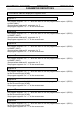
• Ram Address
03:
best displayed in segment mode.
Segments
0
to
7
:
MO - 7
(Landing Calls for Up, 0 to 7).
They show us respectively the state of the contacts of the landing calls for UP. M0 to M7
with the common COMB button.
The corresponding segments are on when the contacts are closed to make a call.
The corresponding segments are off in the reverse case.
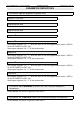
• Ram Address
04
:
best displayed in segment mode.
Segments
0
to
7
:
M8 - 15
(Landing Calls for Up, 8 to 15).
They show us respectively the state of the contacts of the landing calls for UP. M8 to M15
with the common COMB button.
The corresponding segments are on when the contacts are closed to make a call.
The corresponding segments are off in the reverse case.